
Datasheet


±5ppm, I
2
C Real-Time Clock
4 Maxim Integrated
DS3231M
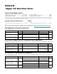
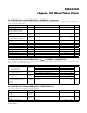
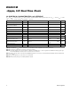
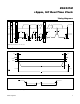
AC ELECTRICAL CHARACTERISTICS—I
2
C INTERFACE
(V
CC
or V
BAT
= +2.3V to +5.5V, T
A
= -45NC to +85NC, unless otherwise noted. Typical values are at V
CC
= +3.3V, V
BAT
= +3.0V,
and T
A
= +25NC, unless otherwise noted.) (Note 6, Figure 1)
Note 2: All voltages are referenced to ground.
Note 3: The parameter t
OSF
is the period of time the oscillator must be stopped for the OSF flag to be set.
Note 4: Includes the temperature conversion current (averaged).
Note 5: This delay applies only if the oscillator is enabled. If the EOSC bit is 1, t
REC
is bypassed and RST immediately goes high.
The state of RST does not affect the I
2
C interface or RTC functions.
Note 6: Interface timing shown is for fast-mode (400kHz) operation. This device is also backward-compatible with standard mode
I
2
C timing.
Note 7: C
B
: Total capacitance of one bus line in picofarads.
Note 8: Guaranteed by design; not 100% production tested.
PARAMETER SYMBOL CONDITIONS MIN TYP MAX UNITS
SCL Clock Frequency f
SCL
0 400 kHz
Bus Free Time Between STOP
and START Conditions
t
BUF
1.3
Fs
Hold Time (Repeated) START
Condition
t
HD:STA
0.6
Fs
Low Period of SCL t
LOW
1.3
Fs
High Period of SCL t
HIGH
0.6
Fs
Data Hold Time t
HD:DAT
0 0.9
Fs
Data Set-Up Time t
SU:DAT
100 ns
START Set-Up Time t
SU:STA
0.6
Fs
SDA and SCL Rise Time t
R
(Note 7)
20 +
0.1C
B
300 ns
SDA and SCL Fall Time t
F
(Note 7)
20 +
0.1C
B
300 ns
STOP Set-Up Time t
SU:STO
0.6
Fs
SDA, SCL Input Capacitance C
BIN
(Note 8) 10 pF