
Datasheet


±5ppm, I
2
C Real-Time Clock
7Maxim Integrated
DS3231M
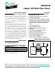
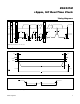
Pin Configuration
Pin Description
16
15
14
13
12
11
10
9
1
2
3
4
5
6
7
8
32KHZ SCL
SDA
V
BAT
GND
N.C.
N.C.
N.C.
N.C.
TOP VIEW
SO
V
CC
INT/SQW
N.C.
RST
N.C.
N.C.
N.C.
DS3231M
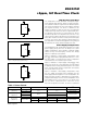
DS3231M
+
V
BAT
GNDRST
1
2
8
7
SCL
SDAV
CC
INT/SQW
32KHZ
SO
TOP VIEW
3
4
6
5
+
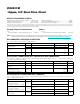
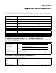
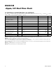
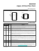
PIN
NAME FUNCTION
8 SO 16 SO
1 1 32KHZ
32.768kHz Output (50% Duty Cycle). This open-drain pin requires an external pullup resistor.
When enabled with the EN32KHZ bit in the Status register (0Fh), this output operates on either
power supply. This pin can be left open circuit if not used.
2 2 V
CC
DC Power Pin for Primary Power Supply. This pin should be decoupled using a 0.1FF to 1.0FF
capacitor. Connect to ground if not used.
3 3
INT/
SQW
Active-Low Interrupt or 1Hz Square-Wave Output. This open-drain pin requires an external pullup
resistor connected to a supply at 5.5V or less. It can be left open if not used. This multifunction
pin is determined by the state of the INTCN bit in the Control register (0Eh). When INTCN is set to
logic 0, this pin outputs a 1Hz square wave. When INTCN is set to logic 1, a match between the
timekeeping registers and either of the alarm registers activates the INT/SQW pin (if the alarm is
enabled). Because the INTCN bit is set to logic 1 when power is first applied, the pin defaults to
an interrupt output with alarms disabled.
4 4
RST
Active-Low Reset. This pin is an open-drain input/output. It indicates the status of V
CC
relative
to the V
PF
specification. As V
CC
falls below V
PF
, the RST pin is driven low. When V
CC
exceeds
V
PF
, for t
RST
, the RST pin is pulled high by the internal pullup resistor. The active-low, open-drain
output is combined with a debounced pushbutton input function. This pin can be activated by a
pushbutton reset request. It has an internal 50kI (R
PU
) nominal value pullup resistor to V
CC
. No
external pullup resistors should be connected. If the oscillator is disabled, t
REC
is bypassed and
RST immediately goes high.
— 5–12 N.C. No Connection. These pins must be connected to ground.
5 13 GND Ground
6 14 V
BAT
Backup Power-Supply Input. When using the device with the V
BAT
input as the primary power source,
this pin should be decoupled using a 0.1FF to 1.0FF low-leakage capacitor. When using the device
with the V
BAT
input as the backup power source, the capacitor is not required. If V
BAT
is not used,
connect to ground. The device is UL recognized to ensure against reverse charging when used with a
primary lithium battery. Go to www.maximintegrated.com/qa/info/ul for more information.