
Datasheet


±5ppm, I
2
C Real-Time Clock
9Maxim Integrated
DS3231M
High-Accuracy Time Base
The temperature sensor, oscillator, and digital adjust-
ment controller logic form the highly accurate time base.
The controller reads the output of the on-board tempera-
ture sensor and adjusts the final 1Hz output to maintain
the required accuracy. The device is trimmed at the
factory to maintain a tight accuracy over the operating
temperature range. When the device is powered by V
CC
,
the adjustment occurs once a second. When the device
is powered by V
BAT
, the adjustment occurs once every
10s to conserve power. Adjusting the 1Hz time base less
often does not affect the device’s long-term timekeeping
accuracy. The device also contains an Aging Offset reg-
ister that allows a constant offset (positive or negative) to
be added to the factory-trimmed adjustment value.
Power-Supply Configurations
The DS3231M can be configured to operate on a single
power supply (using either V
CC
or V
BAT
) or in a dual-
supply configuration, which provides a backup supply
source to keep the timekeeping circuits alive during
absence of primary system power.
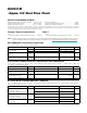
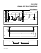
Figure 4 illustrates a single-supply configuration using
V
CC
only, with the V
BAT
input grounded. When V
CC
< V
PF
,
the RST output is asserted (active low). Temperature
conversions are executed once per second.
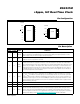
Figure 5 illustrates a single-supply configuration using
V
BAT
only, with the V
CC
input grounded. The RST output
is disabled and is held at ground through the connection
of the internal pullup resistor. Temperature conversions
are executed once every 10s.
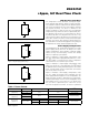
Figure 6 illustrates a dual-supply configuration, using
the V
CC
supply for normal system operation and the
V
BAT
supply for backup power. In this configuration, the
power-selection function is provided by a temperature-
compensated voltage reference and a comparator circuit
that monitors the V
CC
level. When V
CC
is greater than
V
PF
, the device is powered by V
CC
. When V
CC
is less
than V
PF
but greater than V
BAT
, the device is powered
Figure 4. Single Supply (V
CC
Only)
Figure 5. Single Supply (V
BAT
Only)
Figure 6. Dual Power Supply
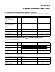
Table 1. Power Control
V
BAT
V
CC
+3.3V
V
BAT
V
CC
V
BAT
V
CC
+3.3V
CONFIGURATION CONDITION I/O ACTIVE I/O INACTIVE
RST
V
CC
Only
(Figure 4)
V
CC
> V
PF
I
CCA
I
CCS
Inactive (High)
V
CC
< V
PF
Active (Low)
V
BAT
Only
(Figure 5)
EOSC = 0
I
BATA
I
BATT
Disabled (Low)
EOSC = 1
I
BATDR
Dual Supply
(Figure 6)
V
CC
> V
PF
I
CCA
I
CCS
Inactive (High)
V
CC
< V
PF
V
CC
> V
BAT
I
CCA
V
CC
> V
BAT
I
CCS
Active (Low)
V
CC
< V
BAT
I
BATA
V
CC
< V
BAT
I
BATT