
Instruction Manual


DS33R11 Ethernet Mapper with Integrated T1/E1/J1 Transceiver
117 of 344
11 DEVICE REGISTERS
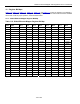
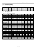
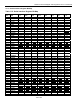
Ten address lines are used to address the register space. Table 11-1 shows the register map for the DS33R11.
The addressable range for the device is 0000h to 08FFh. Each Register Section is 64 bytes deep. Global Registers
are preserved for software compatibility with multiport devices. The Serial Interface (Line) Registers are used to
configure the serial port and the associated transport protocol. The Ethernet Interface (Subscriber) registers are
used to control and observe each of the Ethernet ports. The registers associated with the MAC must be configured
through indirect register write /read access due to the architecture of the device.
When writing to a register input values for unused bits and registers (those designated with “-“) should be zero, as
these bits and registers are reserved. When a register is read from, the values of the unused bits and registers
should be ignored. A latched status bit is set when an event happens and is cleared when read. The register
details are provided in the following tables.
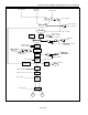
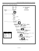
Table 11-1. Register Address Map
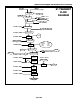
MAPPER/
PORT
CHIP
SELECT
GLOBAL
REGISTERS
ARBITER BERT
SERIAL
INTERFAC
E
ETHERNET
INTERFACE
T1/E1/J1
TRANSCEIVER
Ethernet
Mapper
CS=0,
CST=1
0000h–
003Fh
0040h–
007Fh
0080h–
00BFh
00C0h–
013Fh
0140h– 17Fh —
T1/E1/J1
Port 1
CS=1,
CST=0
— — — — — 000h–0FFh