
Instruction Manual


DS33R11 Ethernet Mapper with Integrated T1/E1/J1 Transceiver
139 of 344
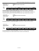
Register Name:
GL.BIS
Register Description:
Global BERT Interrupt Status
Register Address:
0Dh
Bit # 7 6 5 4 3 2 1 0
Name - - - - - - - BIS
Default 0 0 0 0 0 0 0 0
Bit 0: BERT Interrupt Status (BIS) This bit is set to 1 if the BERT has an enabled interrupt generating event.
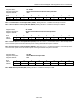
Register Name:
GL.CON1
Register Description:
Connection Register for Ethernet Interface 1
Register Address:
0Eh
Bit # 7 6 5 4 3 2 1 0
Name - - - - - - - LINE1[0]
Default 0 0 0 0 0 0 0 1
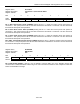
Bit 0: LINE1[0] This bit is preserved to provide software compatibility with multiport devices. The LINE1[0] bit
selects the Ethernet port that is to be connected to the Serial Interface. Note that bidirectional connection is
assumed between the Serial and Ethernet Interfaces. The connection register and corresponding queue size must
be defined for proper operation. Writing a 0 to this register will disconnect the connection. When a connection is
disconnected, “1”s are sourced to the Serial Interface transmit and to the HDLC receiver and the clocks to the
HDLC transmitter/receiver are disabled.