
Instruction Manual


DS33R11 Ethernet Mapper with Integrated T1/E1/J1 Transceiver
141 of 344
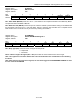
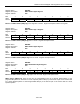
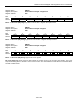
Register Name:
GL.BISTPF
Register Description:
BIST Pass-Fail
Register Address:
21h
Bit # 7 6 5 4 3 2 1 0
Name - - - - - - BISTDN BISTPF
Default 0 0 0 0 0 0 0 0
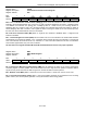
Bit 1: BIST DONE (BISTDN) If this bit is set to 1, the DS33R11 has completed the BIST Test initiated by BISTE.
The pass fail result is available in BISTPF.
Bit 0: BIST Pass-Fail (BISTPF) This bit is equal to 0 after the DS33R11 performs BIST testing on the SDRAM and
the test passes. This bit is set to 1 if the test failed. This bit is valid only after the BIST test is complete and the
BIST DN bit is set. If set this bit can only be cleared by resetting the DS33R11.
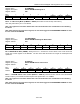
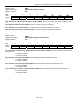
Register Name:
GL.SDMODE1
Register Description:
Global SDRAM Mode Register 1
Register Address:
3Ah
Bit # 7 6 5 4 3 2 1 0
Name - - - - WT BL2 BL1 BL0
Default 0 0 0 0 0 0 1 1
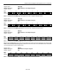
Bit 3: Wrap Type (WT) This bit is used to configure the wrap mode.
0 = Sequential
1 = Interleave
Bits 0- 2: Burst Length 0 through 2 (BL0 – BL2) These bits are used to determine the Burst Length.
Note: This register has a nonzero default value. This should be taken into consideration when initializing
the device.
Note: After changing the value of this register, the user must toggle the GL.SDMODEWS.SDMW bit to write
the new values to the SDRAM.