
Instruction Manual


DS33R11 Ethernet Mapper with Integrated T1/E1/J1 Transceiver
145 of 344
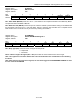
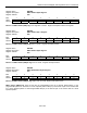
Register Name:
BPCLR
Register Description:
BERT Pattern Configuration Low Register
Register Address:
82h
Bit # 7 6 5 4 3 2 1 0
Name - QRSS PTS PLF4 PLF3 PLF2 PLF1 PLF0
Default 0 0 0 0 0 0 0 0
Bit 6: QRSS Enable (QRSS) When 0, the pattern generator configuration is controlled by PTS, PLF[0:4], and
PTF[0:4], and BSP[0:31]. When 1, the pattern generator configuration is forced to a QRSS pattern with a
generating polynomial of x
20
+ x
17
+ 1. The output of the pattern generator is forced to one if the next fourteen
output bits are all zero.
Bit 5: Pattern Type Select (PTS) When 0, the pattern is a PRBS pattern. When 1, the pattern is a repetitive
pattern.
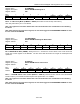
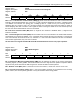
Register Name:
BPCHR
Register Description:
BERT Pattern Configuration High Register
Register Address:
83h
Bit # 7 6 5 4 3 2 1 0
Name - - - PTF4 PTF3 PTF2 PTF1 PTF0
Default 0 0 0 0 0 0 0 0
Bits 4 to 0: Pattern Tap Feedback (PTF[4:0]) These five bits control the PRBS “tap” feedback of the pattern
generator. The “tap” feedback is from bit y of the pattern generator (y = PTF[4:0] +1). These bits are ignored when
programmed for a repetitive pattern. For a PRBS signal, the feedback is an XOR of bit n and bit y. The values
possible are outlined in Section
9.16.