
Instruction Manual


DS33R11 Ethernet Mapper with Integrated T1/E1/J1 Transceiver
151 of 344
11.5 Serial Interface Registers
The Serial Interface contains the Serial HDLC transport circuitry and the associated serial port. The Serial Interface
register map consists of registers that are common functions, transmit functions, and receive functions.
Bits that are
underlined are read-only; all other bits can be written. All reserved registers and bits with “-“
designation should be written to zero, unless specifically noted in the register definition. When read, the information
from reserved registers and bits designated with “-“ should be discarded.
Counter registers are updated by asserting (low to high transition) the associated performance monitoring update
signal (xxPMU). During the counter register update process, the associated performance monitoring status signal
(xxPMS) is deasserted. The counter register update process consists of loading the counter register with the
current count, resetting the counter, forcing the zero count status indication low for one clock cycle, and then
asserting xxPMS. No events are missed during this update procedure.
A latched bit is set when the associated event occurs, and remains set until it is cleared by reading. Once cleared,
a latched bit will not be set again until the associated event occurs again. Reserved configuration bits and registers
should be written to zero.
11.5.1 Serial Interface Transmit and Common Registers
Serial Interface Transmit Registers are used to control the HDLC transmitter associated with each Serial Interface.
The register map is shown in the following Table. Note that throughout this document the HDLC Processor is also
referred to as a “packet processor”.
11.5.1.1 Serial Interface Transmit Register Bit Descriptions
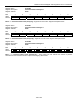
Register Name:
LI.TSLCR
Register Description:
Transmit Serial Interface Configuration Register
Register Address:
0C0h
Bit # 7 6 5 4 3 2 1 0
Name
- - - - - - - TDENPLT
Default
0 0 0 0 0 0 0 0
Bit 0: Transmit Data Enable Polarity (TDENPLT) If set to 1, TDEN is active low for enable. In the default mode,
when TDEN is logic high, the data is enabled and output by the DS33R11.
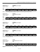
Register Name:
LI.RSTPD
Register Description:
Serial Interface Reset Register
Register Address:
0C1h
Bit # 7 6 5 4 3 2 1 0
Name - - - - - - RESET -
Default 0 0 0 0 0 0 0 0
Bit 1: RESET If this bit set to 1, the Data Path and Control and Status for this interface are reset. The Serial
Interface is held in Reset as long as this bit is high. This bit must be high for a minimum of 200ns for a valid reset
to occur.