
Instruction Manual


DS33R11 Ethernet Mapper with Integrated T1/E1/J1 Transceiver
166 of 344
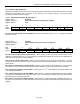
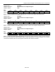
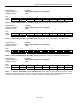
Register Name:
LI.RFPCB0
Register Description:
Receive FCS Errored Packet Count Byte 0 Register
Register Address:
10Ch
Bit # 7 6 5 4 3 2 1 0
Name RFPC7 RFPC6 RFPC5 RFPC4 RFPC3 RFPC2 RFPC1 RFPC0
Default 0 0 0 0 0 0 0 0
Bits 0 – 7: Receive FCS Errored Packet Count (RFPC[7:0]) Eight bits of a 24-bit value. Register description
below.
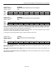
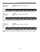
Register Name:
LI.RFPCB1
Register Description:
Receive FCS Errored Packet Count Byte 1 Register
Register Address:
10Dh
Bit # 7 6 5 4 3 2 1 0
Name
RFPC15 RFPC14 RFPC13 RFPC12 RFPC11 RFPC10 RFPC9 RFPC8
Default 0 0 0 0 0 0 0 0
Bits 0 – 7: Receive FCS Errored Packet Count (RFPC[15:8]) Eight bits of a 24-bit value. Register description
below.
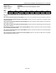
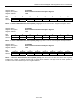
Register Name:
LI.RFPCB2
Register Description:
Receive FCS Errored Packet Count Byte 2 Register
Register Address:
10Eh
Bit # 7 6 5 4 3 2 1 0
Name
RFPC23 RFPC22 RFPC21 RFPC20 RFPC19 RFPC18 RFPC17 RFPC16
Default 0 0 0 0 0 0 0 0
Receive FCS Errored Packet Count (RFPC[23:16]) These twenty-four bits indicate the number of packets
received with an FCS error. The byte count for these packets is included in the receive aborted byte count register
REBCR.