
Instruction Manual


DS33R11 Ethernet Mapper with Integrated T1/E1/J1 Transceiver
219 of 344
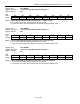
Register Name:
TR.SR3
Register Description:
Status Register 3
Register Address:
1Ah
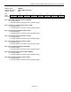
Bit # 7 6 5 4 3 2 1 0
Name LSPARE LDN LUP LOTC LORC V52LNK RDMA RRA
Default 0 0 0 0 0 0 0 0
Bit 7: Spare Code Detected Condition (LSPARE) (T1 Only). Set when the spare code as defined in the
TR.RSCD1/2 registers is being received. See Section
10.19 for details. This is a double interrupt bit. See Section
9.7.
Bit 6: Loop-Down Code Detected Condition (LDN) (T1 Only). Set when the loop down code as defined in the
TR.RDNCD1/2 register is being received. See Section
10.19 for details. This is a double interrupt bit. See Section
9.7.
Bit 5: Loop-Up Code Detected Condition (LUP) (T1 Only). Set when the loop-up code as defined in the
TR.RUPCD1/2 register is being received. See Section
10.19 for details. This is a double interrupt bit. See Section
9.7.
Bit 4: Loss-of-Transmit Clock Condition (LOTC). Set when the TCLKT pin has not transitioned for one channel
time. Forces the LOTC pin high if enabled by TR.CCR1.0. This is a double interrupt bit. See Section
9.7.
Bit 3: Loss-of-Receive Clock Condition (LORC). Set when the RDCLKI pin has not transitioned for one channel
time. This is a double interrupt bit. See Section
9.7.
Bit 2: V5.2 Link Detected Condition (V52LNK) (E1 Only). Set on detection of a V5.2 link identification signal
(G.965). This is a double interrupt bit. See Section
9.7.
Bit 1: Receive Distant MF Alarm Condition (RDMA) (E1 Only). Set when bit 6 of time slot 16 in frame 0 has
been set for two consecutive multiframes. This alarm is not disabled in the CCS signaling mode. This is a double
interrupt bit. See Section
9.7.
Bit 0: Receive Remote Alarm Condition (RRA) (E1 Only). Set when a remote alarm is received at RPOSI and
RNEGI. This is a double interrupt bit. See Section
9.7.