
Instruction Manual


DS33R11 Ethernet Mapper with Integrated T1/E1/J1 Transceiver
225 of 344
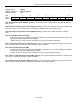
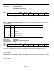
Register Name:
TR.SR6, TR.SR7
Register Description:
HDLC #1 Status Register 6
HDLC #2 Status Register 7
Register Address:
20h, 22h
Bit # 7 6 5 4 3 2 1 0
Name — TMEND RPE RPS RHWM RNE TLWM TNF
Default 0 0 0 0 0 0 0 0
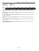
Bit 6: Transmit Message-End Event (TMEND). Set when the transmit HDLC controller has finished sending a
message. This is a latched bit and is cleared when read.
Bit 5: Receive Packet-End Event (RPE). Set when the HDLC controller detects either the finish of a valid
message (i.e., CRC check complete) or when the controller has experienced a message fault such as a CRC
checking error, or an overrun condition, or an abort has been seen. This is a latched bit and is cleared when read.
Bit 4: Receive Packet-Start Event (RPS). Set when the HDLC controller detects an opening byte. This is a
latched bit and is cleared when read.
Bit 3: Receive FIFO Above High-Watermark Condition (RHWM). Set when the receive 128-byte FIFO fills
beyond the high watermark as defined by the receive high-watermark register (TR.RHWMR).
Bit 2: Receive FIFO Not Empty Condition (RNE). Set when the receive 128-byte FIFO has at least 1 byte
available for a read.
Bit 1: Transmit FIFO Below Low-Watermark Condition (TLWM). Set when the transmit 128-byte FIFO empties
beyond the low watermark as defined by the transmit low-watermark register (TR.TLWMR).
Bit 0: Transmit FIFO Not Full Condition (TNF). Set when the transmit 128-byte FIFO has at least 1 byte
available.