
Instruction Manual


DS33R11 Ethernet Mapper with Integrated T1/E1/J1 Transceiver
233 of 344
Register Name:
TR.INFO7
Register Description:
Information Register 7 (Real-Time, Non-Latched Register)
Register Address:
30h
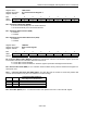
Bit # 7 6 5 4 3 2 1 0
Name CSC5 CSC4 CSC3 CSC2 CSC0 FASSA CASSA CRC4SA
Default 0 0 0 0 0 0 0 0
Bits 3 – 7: CRC4 Sync Counter Bits (CSC0, CSC2 to CSC4). The CRC4 sync counter increments each time the
8ms CRC4 multiframe search times out. The counter is cleared when the framer has successfully obtained
synchronization at the CRC4 level. The counter can also be cleared by disabling the CRC4 mode (TR.E1RCR1.3 =
0). This counter is useful for determining the amount of time the framer has been searching for synchronization at
the CRC4 level. ITU G.706 suggests that if synchronization at the CRC4 level cannot be obtained within 400ms,
then the search should be abandoned and proper action taken. The CRC4 sync counter rolls over. CSC0 is the
LSB of the 6-bit counter. (Note: The bit next to LSB is not accessible. CSC1 is omitted to allow resolution to
>400ms using 5 bits.) These are read-only, non-latched, real-time bits. It is not necessary to precede the read of
these bits with a write.
Bit 2: FAS Sync Active (FASSA). Set while the synchronizer is searching for alignment at the FAS level. This is a
read-only, non-latched, real-time bit. It is not necessary to precede the read of this bit with a write.
Bit 1: CAS MF Sync Active (CASSA). Set while the synchronizer is searching for the CAS MF alignment word.
This is a read-only, non-latched, real-time bit. It is not necessary to precede the read of this bit with a write.
Bit 0: CRC4 MF Sync Active (CRC4SA). Set while the synchronizer is searching for the CRC4 MF alignment
word. This is a read-only, non-latched, real-time bit. It is not necessary to precede the read of this bit with a write.
Register Name:
TR.H1RC, TR.H2RC
Register Description:
HDLC #1 Receive Control
HDLC #2 Receive Control
Register Address:
31h, 32h
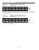
Bit # 7 6 5 4 3 2 1 0
Name RHR RHMS — — — — — RSFD
Default 0 0 0 0 0 0 0 0
Bit 7: Receive HDLC Reset (RHR). Resets the receive HDLC controller and flushes the receive FIFO. Must be
cleared and set again for a subsequent reset.
0 = normal operation
1 = reset receive HDLC controller and flush the receive FIFO
Bit 6: Receive HDLC Mapping Select (RHMS)
0 = receive HDLC assigned to channels
1 = receive HDLC assigned to FDL (T1 mode), Sa bits (E1 mode)
Bits 1 – 5: Unused, must be set to 0 or proper operation
Bit 0: Receive SS7 Fill-In Signal Unit Delete (RSFD)
0 = normal operation; all FISUs are stored in the receive FIFO and reported to the host.
1 = When a consecutive FISU having the same BSN the previous FISU is detected, it is deleted without
host intervention.