
Instruction Manual


DS33R11 Ethernet Mapper with Integrated T1/E1/J1 Transceiver
238 of 344
Register Name:
TR.SIGCR
Register Description:
Signaling Control Register
Register Address:
40h
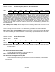
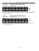
Bit # 7 6 5 4 3 2 1 0
Name GRSRE — — RFE RFF RCCS TCCS FRSAO
Default 0 0 0 0 0 0 0 0
Bit 7: Global Receive Signaling Reinsertion Enable (GRSRE). This bit allows the user to reinsert all signaling
channels without programming all channels through the per-channel function.
0 = do not reinsert all signaling
1 = reinsert all signaling
Bit 4: Receive Freeze Enable (RFE). See Section
10.9.2.3 for details.
0 = no freezing of receive signaling data occurs
1 = allow freezing of receive signaling data at RSIG (and RSERO if receive signaling reinsertion is
enabled)
Bit 3: Receive Force Freeze (RFF). Freezes receive-side signaling at RSIG (and RSERO if receive signaling
reinsertion is enabled); overrides receive freeze enable (RFE). See Section
10.9.2.3 for details.
0 = do not force a freeze event
1 = force a freeze event
Bit 2: Receive Time Slot Control for CAS Signaling (RCCS). Controls the order that signaling is placed into the
receive signaling registers. This bit should be set = 0 in T1 mode.
0 = signaling data is CAS format
1 = signaling data is CCS format
Bit 1: Transmit Time Slot Control for CAS Signaling (TCCS). Controls the order that signaling is transmitted
from the transmit signaling registers. This bit should be set = 0 in T1 mode.
0 = signaling data is CAS format
1 = signaling data is CCS format
Bit 0: Force Receive Signaling All Ones (FRSAO). In T1 mode, this bit forces all signaling data at the RSIG and
RSERO pin to all ones. This bit has no effect in E1 mode.
0 = normal signaling data at RSIG and RSERO
1 = force signaling data at RSIG and RSERO to all ones