
Instruction Manual


DS33R11 Ethernet Mapper with Integrated T1/E1/J1 Transceiver
239 of 344
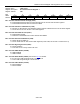
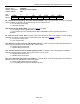
Register Name:
TR.ERCNT
Register Description:
Error-Counter Configuration Register
Register Address:
41h
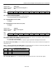
Bit # 7 6 5 4 3 2 1 0
Name — MECU ECUS EAMS VCRFS FSBE MOSCRF LCVCRF
Default 0 0 0 0 0 0 0 0
Bit 6: Manual Error-Counter Update (MECU). When enabled by TR.ERCNT.4, the changing of this bit from a 0 to
a 1 allows the next clock cycle to load the error-counter registers with the latest counts and reset the counters. The
user must wait a minimum of 1.5 RCLKO clock periods before reading the error count registers to allow for proper
update.
Bit 5: Error-Counter Update Select (ECUS)
T1 Mode:
0 = update error counters once a second
1 = update error counters every 42ms (333 frames)
E1 Mode:
0 = update error counters once a second
1 = update error counters every 62.5ms (500 frames)
Bit 4: Error-Accumulation Mode Select (EAMS)
0 = TR.ERCNT.5 determines accumulation time
1 = TR.ERCNT.6 determines accumulation time
Bit 3: E1 Line-Code Violation Count Register Function Select (VCRFS)
0 = count bipolar violations (BPVs)
1 = count code violations (CVs)
Bit 2: PCVCR Fs-Bit Error-Report Enable (FSBE)
0 = do not report bit errors in Fs-bit position; only Ft-bit position
1 = report bit errors in Fs-bit position as well as Ft-bit position
Bit 1: Multiframe Out-of-Sync Count Register Function Select (MOSCRF)
0 = count errors in the framing bit position
1 = count the number of multiframes out-of-sync
Bit 0: T1 Line-Code Violation Count Register Function Select (LCVCRF)
0 = do not count excessive 0s
1 = count excessive 0s