
Instruction Manual


DS33R11 Ethernet Mapper with Integrated T1/E1/J1 Transceiver
253 of 344
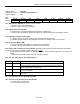
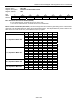
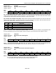
Register Name:
TR.CCR4
Register Description:
Common Control Register 4
Register Address:
73h
Bit # 7 6 5 4 3 2 1 0
Name RLT3 RLT2 RLT1 RLT0 — — — —
Default 0 0 0 0 0 0 0 0
Bits 4 – 7: Receive Level Threshold Bits (RLT0 to RLT3)
RLT3 RLT2 RLT1 RLT0 Receive Level (dB)
0 0 0 0 Greater than -2.5
0 0 0 1 -2.5
0 0 1 0 -5.0
0 0 1 1 -7.5
0 1 0 0 -10.0
0 1 0 1 -12.5
0 1 1 0 -15.0
0 1 1 1 -17.5
1 0 0 0 -20.0
1 0 0 1 -22.5
1 0 1 0 -25.0
1 0 1 1 -27.5
1 1 0 0 -30.0
1 1 0 1 -32.5
1 1 1 0 -35.0
1 1 1 1 Less than -37.5
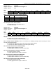
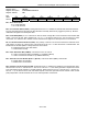
Register Name:
TR.TDS0SEL
Register Description:
Transmit Channel Monitor Select
Register Address:
74h
Bit # 7 6 5 4 3 2 1 0
Name — — — TCM4 TCM3 TCM2 TCM1 TCM0
Default 0 0 0 0 0 0 0 0
Bits 0 – 4: Transmit Channel Monitor Bits (TCM0 to TCM4). TCM0 is the LSB of a 5-bit channel select that
determines which transmit channel data appear in the TR.TDS0M register.