
Instruction Manual


DS33R11 Ethernet Mapper with Integrated T1/E1/J1 Transceiver
256 of 344
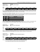
Register Name:
TR.TLBC
Register Description:
Transmit Line Build-Out Control
Register Address:
7Dh
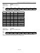
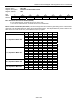
Bit # 7 6 5 4 3 2 1 0
Name — AGCE GC5 GC4 GC3 GC2 GC1 GC0
Default 0 0 0 0 0 0 0 0
Bit 6: Automatic Gain Control Enable (AGCE).
0 = use Transmit AGC, TR.TLBC bits 0–5 are “don’t care”
1 = do not use Transmit AGC, TR.TLBC bits 0–5 set nominal level
Bits 0–5: Gain Control Bits (GC0–GC5). The GC0 through GC5 bits control the gain setting for the nonautomatic
gain mode. Use the tables below for setting the recommended values. The LB (line build-out) column refers to the
value in the L0–L2 bits in TR.LIC1 (Line Interface Control 1) register.
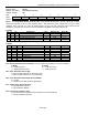
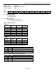
NETWORK MODE LB GC5 GC4 GC3 GC2 GC1 GC0
0 1 0 0 1 1 0
1 0 1 1 0 1 1
2 0 1 1 0 1 0
3 1 0 0 0 0 0
4 1 0 0 1 1 1
5 1 0 0 1 1 1
6 0 1 0 0 1 1
T1, Impedance Match Off
7 1 1 1 1 1 1
0 0 1 1 1 1 0
1 0 1 0 1 0 1
2 0 1 0 1 0 1
3 0 1 1 0 1 0
4 1 0 0 0 1 0
5 1 0 0 0 0 0
6 0 0 1 1 0 0
T1, Impedance Match On
7 1 1 1 1 1 1
0 1 0 0 0 0 1
1 1 0 0 0 0 1
4 1 0 1 0 1 0
E1, Impedance Match Off
5 1 0 1 0 0 0
0 0 1 1 0 1 0
E1, Impedance Match On
1 0 1 1 0 1 0