
Instruction Manual


DS33R11 Ethernet Mapper with Integrated T1/E1/J1 Transceiver
258 of 344
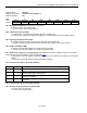
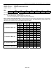
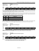
Register Name:
TR.LIC3
Register Description:
Line Interface Control 3
Register Address:
7Ah
Bit # 7 6 5 4 3 2 1 0
Name
—
TCES RCES MM1 MM0 RSCLKE TSCLKE TAOZ
Default 0 0 0 0 0 0 0 0
Bit 6: Transmit-Clock Edge Select (TCES). Selects which TDCLKI edge to sample TPOSI and TNEGI.
0 = sample TPOSI and TNEGI on falling edge of TDCLKI
1 = sample TPOSI and TNEGI on rising edge of TDCLKI
Bit 5: Receive-Clock Edge Select (RCES). Selects which RDCLKO edge to update RPOSO and RNEGO.
0 = update RPOSO and RNEGO on rising edge of RDCLKO
1 = update RPOSO and RNEGO on falling edge of RDCLKO
Bits 3 – 4: Monitor Mode (MM0 to MM1)
MM1 MM0
Internal Linear Gain Boost
(dB)
0 0 Normal operation (no boost)
0 1 20
1 0 26
1 1 32
Bit 2: Receive Synchronization G.703 Clock Enable (RSCLKE)
0 = disable 1.544MHz (T1)/2.048MHz (E1) synchronization receive mode
1 = enable 1.544MHz (T1)/2.048MHz (E1) synchronization receive mode
Bit 1: Transmit Synchronization G.703 Clock Enable (TSCLKE)
0 = disable 1.544MHz (T1)/2.048MHz (E1) transmit synchronization clock
1 = enable 1.544MHz (T1)/2.048MHz (E1) transmit synchronization clock
Bit 0: Transmit Alternate Ones and Zeros (TAOZ). Transmit a …101010… pattern (customer disconnect
indication signal) at TTIP and TRING. The transmission of this data pattern is always timed off of TCLKT.
0 = disabled
1 = enabled