
Instruction Manual


DS33R11 Ethernet Mapper with Integrated T1/E1/J1 Transceiver
259 of 344
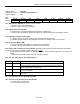
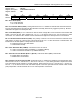
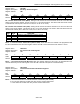
Register Name:
TR.LIC4
Register Description:
Line Interface Control 4
Register Address:
7Bh
Bit # 7 6 5 4 3 2 1 0
Name CMIE CMII MPS1 MPS0 TT1 TT0 RT1 RT0
Default 0 0 0 0 0 0 0 0
Bit 7: CMI Enable (CMIE)
0 = disable CMI mode
1 = enable CMI mode
Bit 6: CMI Invert (CMII)
0 = CMI normal at TTIP and RTIP
1 = invert CMI signal at TTIP and RTIP
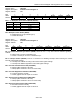
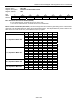
Bits 4 – 5: MCLK Prescaler
T1 Mode:
MCLK (MHz) MPS1 MPS0
JAMUX
(TR.LIC2.3)
1.544 0 0 0
3.088 0 1 0
6.176 1 0 0
12.352 1 1 0
2.048 0 0 1
4.096 0 1 1
8.192 1 0 1
16.384 1 1 1
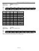
E1 Mode:
MCLK
(MHz)
MPS1 MPS0
JAMUX
(TR.LIC2.3)
2.048 0 0 0
4.096 0 1 0
8.192 1 0 0
16.384 1 1 0
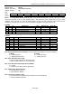
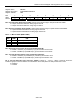
Bits 2 – 3: Transmit Termination Select (TT0, TT1)
TT1 TT0 Internal Transmit-Termination Configuration
0
0
Internal transmit-side termination disabled
0 1
Internal transmit -side 75Ω enabled
1 0
Internal transmit -side 100Ω enabled
1 1
Internal transmit -side 120Ω enabled
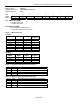
Bits 0 – 1: Receive Termination Select (RT0, RT1)
RT1 RT0 Internal Receive-Termination Configuration
0 0 Internal receive-side termination disabled
0 1
Internal receive-side 75Ω enabled
1 0
Internal receive-side 100Ω enabled
1 1
Internal receive-side 120Ω enabled