
Instruction Manual


DS33R11 Ethernet Mapper with Integrated T1/E1/J1 Transceiver
270 of 344
Register Name:
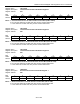
TR.H1TTSBS, TR.H2TTSBS
Register Description:
HDLC # 1 Transmit Time Slot Bits/Sa Bits Select
HDLC # 2 Transmit Time Slot Bits/Sa Bits Select
Register Address:
9Bh, ABh
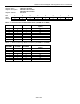
Bit # 7 6 5 4 3 2 1 0
Name TCB8SE TCB7SE TCB6SE TCB5SE TCB4SE TCB3SE TCB2SE TCB1SE
Default 0 0 0 0 0 0 0 0
Bit 7: Transmit Channel Bit 8 Suppress Enable (TCB1SE). MSB of the channel. Set to 1 to stop this bit from
being used.
Bit 6: Transmit Channel Bit 7 Suppress Enable (TCB1SE). Set to 1 to stop this bit from being used.
Bit 5: Transmit Channel Bit 6 Suppress Enable (TCB1SE). Set to 1 to stop this bit from being used.
Bit 4: Transmit Channel Bit 5 Suppress Enable/Sa4 Bit Enable (TCB1SE). Set to 1 to stop this bit from being
used.
Bit 3: Transmit Channel Bit 4 Suppress Enable/Sa5 Bit Enable (TCB1SE). Set to 1 to stop this bit from being
used.
Bit 2: Transmit Channel Bit 3 Suppress Enable/Sa6 Bit Enable (TCB1SE). Set to 1 to stop this bit from being
used.
Bit 1: Transmit Channel Bit 2 Suppress Enable/Sa7 Bit Enable (TCB1SE). Set to 1 to stop this bit from being
used.
Bit 0: Transmit Channel Bit 1 Suppress Enable/Sa8 Bit Enable (TCB1SE). LSB of the channel. Set to 1 to stop
this bit from being used.
Register Name:
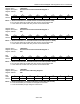
TR.H1RPBA, TR.H2RPBA
Register Description:
HDLC # 1 Receive Packet Bytes Available
HDLC # 2 Receive Packet Bytes Available
Register Address:
9Ch, ACh
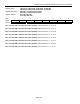
Bit # 7 6 5 4 3 2 1 0
Name MS RPBA6 RPBA5 RPBA4 RPBA3 RPBA2 RPBA1 RPBA0
Default 0 0 0 0 0 0 0 0
Bit 7: Message Status (MS)
0 = bytes indicated by RPBA0 through RPBA6 are the end of a message. Host must check the INFO5 or
INFO6 register for details.
1 = bytes indicated by RPBA0 through RPBA6 are the beginning or continuation of a message. The host
does not need to check the INFO5 or INFO6 register.
Bits 0 – 6: Receive FIFO Packet Bytes Available Count (RPBA0 to RPBA6). RPBA0 is the LSB.