
Instruction Manual

DS33R11 Ethernet Mapper with Integrated T1/E1/J1 Transceiver
293 of 344
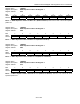
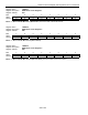
Register Name:
TR.BC2
Register Description:
BERT Control Register 2
Register Address:
E1h
Bit # 7 6 5 4 3 2 1 0
Name EIB2 EIB1 EIB0 SBE RPL3 RPL2 RPL1 RPL0
Default 0 0 0 0 0 0 0 0
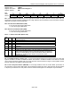
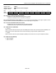
Bits 5 – 7: Error Insert Bits 0 to 2 (EIB0 to EIB2). Automatically inserts bit errors at the prescribed rate into the
generated data pattern. Can be used for verifying error-detection features.
EIB2 EIB1 EIB0 Error Rate Inserted
0 0 0 No errors automatically inserted
0 0 1 10E-1
0 1 0 10E-2
0 1 1 10E-3
1 0 0 10E-4
1 0 1 10E-5
1 1 0 10E-6
1 1 1 10E-7
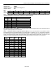
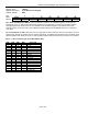
Bit 4: Single Bit-Error Insert (SBE). A low-to-high transition creates a single-bit error. Must be cleared and set
again for a subsequent bit error to be inserted.
Bits 0 – 3: Repetitive Pattern Length Bit 3 (RPL0 to RPL3). RPL0 is the LSB and RPL3 is the MSB of a nibble
that describes how long the repetitive pattern is. The valid range is 17 (0000) to 32 (1111). These bits are ignored if
the receive BERT is programmed for a pseudorandom pattern. To create repetitive patterns fewer than 17 bits in
length, the user must set the length to an integer number of the desired length that is less than or equal to 32. For
example, to create a 6-bit pattern, the user can set the length to 18 (0001) or to 24 (0111) or to 30 (1101).
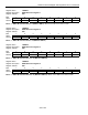
Length
(bits)
RPL3 RPL2 RPL1 RPL0
17 0 0 0 0
18 0 0 0 1
19 0 0 1 0
20 0 0 1 1
21 0 1 0 0
22 0 1 0 1
23 0 1 1 0
24 0 1 1 1
25 1 0 0 0
26 1 0 0 1
27 1 0 1 0
28 1 0 1 1
29 1 1 0 0
30 1 1 0 1
31 1 1 1 0
32 1 1 1 1