
Instruction Manual

DS33R11 Ethernet Mapper with Integrated T1/E1/J1 Transceiver
31 of 344
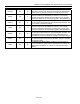
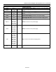
NAME PIN TYPE FUNCTION
T1/E1/J1 ANALOG LINE INTERFACE
TTIP R1, R2 O
Transmit Analog Tip Output for the T1/E1/J1 Transceiver:
Analog line-driver outputs. Two connections are provided to
improve signal quality. These pins connect via a 1:2 step-up
transformer to the network. See Section
10.24 for details.
TRING T1,T2 O
Transmit Analog Ring Output for the T1/E1/J1 Transceiver:
Analog line-driver outputs. Two connections are provided to
improve signal quality. These pins connect via a 1:2 step-up
transformer to the network. See Section
10.24 for details.
RTIP K1 I
Receive Analog Tip Input for the T1/E1/J1 Transceiver: Analog
input for clock recovery circuitry. These pins connect via a 1:1
transformer to the network. See Section
10.24 for details
RRING M1 I
Receive Analog Ring Input for the T1/E1/J1 Transceiver:
Analog input for clock recovery circuitry. These pins connect via a
1:1 transformer to the network. See Section
10.24 for details
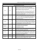
T1/E1/J1 TRANSMIT FRAMER INTERFACE
TSERI E3 I
Transmit Serial Data Input to the T1/E1/J1 Framer: Transmit
NRZ serial data. Sampled on the falling edge of TCLKT when the
transmit-side elastic store is disabled. Sampled on the falling edge
of TSYSCLK when the transmit-side elastic store is enabled.
TCLKT D2 I
Transmit Clock for the T1/E1/J1 Transceiver: 1.544MHz or a
2.048MHz primary clock. Used to clock data from the TSERI pin
through the transmit-side formatter.
TCHBLK A2 O
Transmit Channel Block for the T1/E1/J1 Transceiver: A user-
programmable output that can be forced high or low during any of
the channels. Synchronous with TCLKT when the transmit-side
elastic store is disabled. Synchronous with TSYSCLK when the
transmit-side elastic store is enabled. Useful for locating individual
channels in drop-and-insert applications, for external per-channel
loopback, and for per-channel conditioning.
TCHCLK G1 O
Transmit Channel Clock for the T1/E1/J1 Transceiver: A
192kHz (T1) or 256kHz (E1) clock that pulses high during the LSB
of each channel. Can also be programmed to output a gated
transmit-bit clock for fractional T1/E1 applications. Synchronous
with TCLKT when the transmit-side elastic store is disabled.
Synchronous with TSYSCLK when the transmit-side elastic store is
enabled. Useful for parallel-to-serial conversion of channel data.
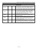
TSSYNC A5 I
Transmit System Sync for the T1/E1/J1 Transceiver: Only used
when the transmit-side elastic store is enabled. A pulse at this pin
will establish either frame or multiframe boundaries for the transmit
side. Should be tied low in applications that do not use the transmit-
side elastic store.
TSYNC C1 I/O
Transmit Sync for the T1/E1/J1 Transceiver: A pulse at this pin
will establish either frame or multiframe boundaries for the transmit
side. Can be programmed to output either a frame or multiframe
pulse. If this pin is set to output pulses at frame boundaries, it can
also be set via TR.IOCR1.3 to output double-wide pulses at
signaling frames in T1 mode.
TSYSCLK E4 I
Transmit System Clock for the T1/E1/J1 Transceiver:
1.544MHz, 2.048MHz, 4.096MHz, 8.192MHz, or 16.384MHz clock.
Only used when the transmit-side elastic-store function is enabled.
Should be tied low in applications that do not use the transmit-side
elastic store.