
Instruction Manual

DS33R11 Ethernet Mapper with Integrated T1/E1/J1 Transceiver
339 of 344
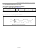
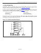
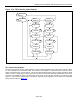
Figure 14-2. TAP Controller State Diagram
1
0
0
1
11
1
1
1
11
11
11
00
0
0
0
1
0
0
00
1
1
00
0
0
Select
DR-Scan
Capture DR
Shift DR
Exit DR
Pause DR
Exit2 DR
Update DR
Select
IR-Scan
Capture IR
Shift IR
Exit IR
Pause IR
Exit2 IR
Update IR
Test Logic
Reset
Run Test/
Idle
0
14.2 Instruction Register
The instruction register contains a shift register as well as a latched parallel output and is 3 bits in length. When
the TAP controller enters the Shift-IR state, the instruction shift register is connected between JTDI and JTDO.
While in the Shift-IR state, a rising edge on JTCLK with JTMS LOW will shift the data one stage towards the serial
output at JTDO. A rising edge on JTCLK in the Exit1-IR state or the Exit2-IR state with JTMS HIGH will move the
controller to the Update-IR state. The falling edge of that same JTCLK will latch the data in the instruction shift
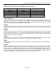
register to the instruction parallel output. Instructions supported by the DS26521 and its respective operational
binary codes are shown in
Table 14-1.