
Instruction Manual

DS33R11 Ethernet Mapper with Integrated T1/E1/J1 Transceiver
341 of 344
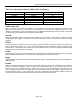
14.3 JTAG ID Codes
Table 14-2. ID Code Structure
DEVICE
REVISION
ID[31:28]
DEVICE CODE
ID[27:12]
MANUFACTURER’S CODE
ID[11:1]
REQUIRED
ID[0]
Ethernet
Mapper
0000 0000 0000 0110 0001 000 1010 0001 1
T1/E1/J1
Transceiver
0000 0000 0000 0001 0000 000 1010 0001 1
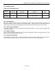
14.4 Test Registers
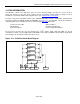
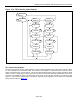
IEEE 1149.1 requires a minimum of two test registers: the bypass register and the boundary scan register. An
optional test register has been included with the DS26521 design. This test register is the identification register
and is used in conjunction with the IDCODE instruction and the Test-Logic-Reset state of the TAP controller.
14.4.1 Boundary Scan Register
This register contains both a shift register path and a latched parallel output for all control cells and digital I/O cells
and is n bits in length.
14.4.2 Bypass Register
This is a single one-bit shift register used in conjunction with the BYPASS, CLAMP, and HIGHZ instructions, which
provides a short path between JTDI and JTDO.
14.4.3 Identification Register
The identification register contains a 32-bit shift register and a 32-bit latched parallel output. This register is
selected during the IDCODE instruction and when the TAP controller is in the Test-Logic-Reset state.