
Instruction Manual
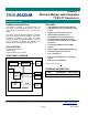

DS33R11 Ethernet Mapper with Integrated T1/E1/J1 Transceiver
7 of 344
Figure 12-19. Transmit-Side 2.048MHz Boundary Timing (Elastic Store Enabled)................................................ 307
Figure 12-20. Receive-Side Timing ......................................................................................................................... 308
Figure 12-21. Receive-Side Boundary Timing (with Elastic Store Disabled) .......................................................... 308
Figure 12-22. Receive-Side Boundary Timing, RSYSCLK = 1.544MHz (E-Store Enabled)................................... 309
Figure 12-23. Receive-Side Boundary Timing, RSYSCLK = 2.048MHz (E-Store Enabled)................................... 309
Figure 12-24. G.802 Timing, E1 Mode Only............................................................................................................ 310
Figure 12-25. Transmit-Side Timing ........................................................................................................................ 310
Figure 12-26. Transmit-Side Boundary Timing (Elastic Store Disabled)................................................................. 311
Figure 12-27. Transmit-Side Boundary Timing, TSYSCLK = 1.544MHz (Elastic Store Enabled) ......................... 311
Figure 12-28. Transmit-Side Boundary Timing, TSYSCLK = 2.048MHz (Elastic Store Enabled) .......................... 312
Figure 13-1. Transmit MII Interface Timing ............................................................................................................. 315
Figure 13-2. Receive MII Interface Timing .............................................................................................................. 316
Figure 13-3. Transmit RMII Interface Timing........................................................................................................... 317
Figure 13-4. Receive RMII Interface Timing............................................................................................................ 318
Figure 13-5. MDIO Interface Timing ........................................................................................................................ 319
Figure 13-6. Transmit WAN Interface Timing.......................................................................................................... 320
Figure 13-7. Receive WAN Interface Timing........................................................................................................... 321
Figure 13-8. SDRAM Interface Timing .................................................................................................................... 323
Figure 13-9. Intel Bus Read Timing (MODEC = 00)................................................................................................ 325
Figure 13-10. Intel Bus Write Timing (MODEC = 00).............................................................................................. 325
Figure 13-11. Motorola Bus Read Timing (MODEC = 01) ...................................................................................... 326
Figure 13-12. Motorola Bus Write Timing (MODEC = 01)....................................................................................... 326
Figure 13-13. Receive-Side Timing ......................................................................................................................... 328
Figure 13-14. Receive-Side Timing, Elastic Store Enabled .................................................................................... 329
Figure 13-15. Receive Line Interface Timing .......................................................................................................... 330
Figure 13-16. Receive Timing Delay RCLKO to BPCLK......................................................................................... 331
Figure 13-17. Transmit-Side Timing ........................................................................................................................ 333
Figure 13-18. Transmit-Side Timing, Elastic Store Enabled ................................................................................... 334
Figure 13-19. Transmit Line Interface Timing ......................................................................................................... 334
Figure 13-20. JTAG Interface Timing Diagram ....................................................................................................... 335
Figure 14-1. JTAG Functional Block Diagram......................................................................................................... 336
Figure 14-2. TAP Controller State Diagram............................................................................................................. 339
Figure 14-3. JTAG Functional Timing...................................................................................................................... 342