
Datasheet

DS4830
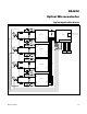
Optical Microcontroller
21Maxim Integrated
allows the application to develop custom loader software
that can operate under the control of the application soft-
ware. The utility ROM contains firmware-accessible flash
programming functions that erase and program flash
memory. These functions are described in detail in the
DS4830 User’s Guide.
Register Set
Sets of registers control most device functions. These
registers provide a working space for memory opera-
tions as well as configuring and addressing peripheral
registers on the device. Registers are divided into two
major types: system registers (special-purpose registers,
or SPRs) and peripheral registers (special-function reg-
isters, or SFRs). The common register set, also known
as the system registers, includes the ALU, accumulator
registers, data pointers, interrupt vectors and control,
and stack pointer. The peripheral registers define addi-
tional functionality, and the functionality is broken up
into discrete modules. Both the system registers and the
peripheral registers are described in detail in the DS4830
User’s Guide.
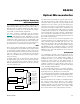
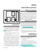
System Timing
The device generates its 10MHz instruction clock
(MOSC) internally. On power-up, the oscillator’s output
(which cannot be accessed externally) is disabled until
V
DD
rises above V
BO
. Once this threshold is reached, the
output is enabled after approximately 1ms, clocking the
device. See Figure 8.
System Reset
The device features several sources that can be used to
reset the DS4830.
Power-On Reset
An internal power-on-reset (POR) circuit is used to
enhance system reliability. This circuit forces the device
to perform a POR whenever a rising voltage on V
DD
climbs above V
BO
. When this happens the following
events occur:
• Allregistersandcircuitsentertheirresetstate.
• ThePORflag(WDCN.7)issettoindicatethesource
of the reset.
• Code execution begins at location 8000h when the
reset condition is released.
Brownout Detect/Reset
The device features a brownout detect/reset function.
Whenever the power monitor detects a brownout condi-
tion (when V
DD
< V
BO
), it immediately issues a reset and
stays in that state as long as V
DD
remains below V
BO
.
Once V
DD
voltage rises above V
BO
, the device waits
for t
SU:MOSC
before returning to normal operation, also
referred to as CPU state. If a brownout occurs during
t
SU:MOSC
, the device again goes back to the brownout
state. Otherwise, it enters into CPU state. In CPU state,
the brownout detector is also enabled.
On power-up, the device always enters brownout state
first and then follows the above sequence. The reset
issued by brownout is the same as POR. Any action
performed after POR also happens on brownout reset.
Figure 8. System Timing
t
SU:MOSC
= ~1ms
CORE
CLOCK
V
DD
V
BO