
Datasheet


DS5000(T)
18 of 19
NOTES:
1. All voltages are referenced to ground.
2. Maximum operating I
CC
is measured with all output pins disconnected; XTAL1 driven with t
CLKR
,
t
CLKF
= 10 ns, V
IL
= 0.5V; XTAL2 disconnected; EA = RST = PORT0 = V
CC
.
3. Idle mode I
CC
is measured with all output pins disconnected; XTAL1 driven with t
CLKR
, t
CLKF
= 10 ns,
V
IL
= 0.5V; XTAL2 disconnected; EA = PORT0 = V
CC
, RST = V
SS
.
4. Stop mode I
CC
is measured with all output pins disconnected; EA = PORT0 = V
CC
; XTAL2 not
connected; RST = V
SS
.
5. Crystal start-up time is the time required to get the mass of the crystal into vibrational motion from
the time that power is first applied to the circuit until the first clock pulse is produced by the on-chip
oscillator. The user should check with the crystal vendor for the worst case spec on this time.
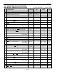
PACKAGE DRAWING
INCHES
DIM
MIN MAX
A IN. 2.080 2.100
B IN. 0.680 0.700
C IN. 0.290 0.325
D IN. 0.090 0.110
E IN. 0.030 0.060
F IN. 0.145 0.185
G IN. 0.016 0.020
H IN. 0.590 0.610
I IN. 0.009 0.015