
Datasheet


DS80C310
10 of 22
PERIPHERAL OVERVIEW
The DS80C310 provides the same peripheral functions as the standard 80C32. The device is compatible
with the DS80C320, but it does not offer all the peripherals.
TIMER RATE CONTROL
There is one important difference between the DS80C310 and 8051 regarding timers. The original 8051
used 12 clocks per cycle for timers and machine cycles. The DS80C310 architecture normally uses 4
clocks per machine cycle. However, in the area of timers and serial ports, the DS80C310 defaults to 12
clocks per cycle on reset. This allows existing code with real-time dependencies such as baud rates to
operate properly.
If an application needs higher speed timers or serial baud rates, the user can select individual timers to run
at the 4-clock rate. The Clock Control Register (CKCON; 8Eh) determines these timer speeds. When the
relevant CKCON bit is logic 1, the DS80C310 uses 4 clocks per cycle to generate timer speeds. When the
bit is 0, the DS80C310 uses 12 clocks for timer speeds. The reset condition is 0. CKCON.5 selects the
speed of Timer 2. CKCON.4 selects Timer 1 and CKCON.3 selects Timer 0. Note that unless a user
desires very fast timing, it is unnecessary to alter these bits. Also note that the timer controls are
independent.
POWER-ON RESET
The DS80C310 holds itself in reset during a power-up until 65,536 clock cycles have elapsed. The power-
on reset used by the DS80C310 differs somewhat from other members of the high-speed microcontroller
family. The crystal oscillator can start anywhere between 1.0V and 4.5V, but is not specified. This
eliminates the need for an RC reset circuit. For voltage-specific precision-brownout detection, an external
component is needed. When the device goes through a power-on reset, the POR flag is set in the
WDCON (D8h) register at bit 6.
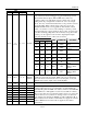
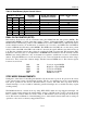
INTERRUPTS
The DS80C310 provides 10 interrupt sources with two priority levels. Software can assign high or low
priority to all sources. All interrupts that are new to the 8051 have a lower natural priority than the
originals.
Table 3. Interrupt Sources and Priorities
NAME DESCRIPTION VECTOR
NAT
URAL
PRIORITY
INT0
External Interrupt 0 03h 1
TF0 Timer 0 0Bh 2
INT1
External Interrupt 1 13h 3
TF1 Timer 1 1Bh 4
SCON T1 or R1 from the serial port 23h 5
TF2 Timer 2 2Bh 6
INT2 External Interrupt 2 43h 7
INT3
External Interrupt 3 4Bh 8
INT4 External Interrupt 4 53h 9
INT5
External Interrupt 5 5Bh 10