
Datasheet


DS80C310
3 of 22
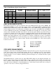
PIN DESCRIPTION
PIN
PDIP PLCC TQFP
NAME
FUNCTION
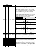
Port 1 (I/O). Port 1 functions as both an 8-bit bidirectional I/O port
and an alternate functional interface for Timer 2 I/O and new
external interrupts. The reset condition of Port 1 is with all bits at
logic 1. In this state, a weak pullup holds the port high. This
condition also serves as an input mode, since any external circuit
that writes to the port overcomes the weak pullup. When software
writes a 0 to any port pin, the DS80C310 activates a strong pulldown
that remains on until either a 1 is written or a reset occurs. Writing a
1 after the port has been at 0 causes a strong transition driver to turn
on, followed by a weaker sustaining pullup. Once the momentary
strong driver turns off, the port once again becomes the output high
(and input) state. The alternate modes of Port 1 are outlined as
follows:
PIN
PDIP PLCC TQFP
PORT ALTERNATE FUNCTION
1 2 40 P1.0 T2
External I/O for
Timer/Counter 2
2 3 41 P1.1 T2EX
Timer/Counter 2
Capture/Reload
Trigger
3 4 42 P1.2 —
DS80C320 has a serial
port RXD
4 5 43 P1.3 —
DS80C320 has a serial
port TXD
5 6 44 P1.4 INT2
External Interrupt 2
(Positive Edge Detect)
6 7 1 P1.5
INT3
External Interrupt 3
(Negative Edge
Detect)
7 8 2 P1.6 INT4
External Interrupt 4
(Positive Edge Detect)
1–8 2–9
40–44,
1, 2, 3
P1.0–P1.7
8 9 3 P1.7
INT5
External Interrupt 5
(Negative Edge
Detect)
9 10 4 RST
Reset (Input). The RST input pin contains a Schmitt voltage input to
recognize external active-high reset inputs. The pin also employs an
internal pulldown resistor to allow for a combination of wired-OR
external reset sources.