
Datasheet


DS9490R/DS9490B
PIN CONFIGURATION
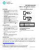
Figure 4. 1-Wire RJ11 SOCKET FOR DS9490R
PIN
SIGNAL
NAME
DESCRIPTION
1
V
DD
5VDC Output
2
GND Power Ground
3
OW 1-Wire Data
4
GND_OW 1-Wire Return
5
SUSO
USB Suspend Output
6
N.C. No Connection
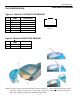
Figure 5. iButton SOCKET FOR DS9490B
PIN
SIGNAL
NAME
DESCRIPTION
1
OW 1-Wire Data
2
GND_OW 1-Wire Return
*Note: The data contact faces down and away from the embossed ‘i’. Once the iButton is inserted in the
enclosure, snap the end cap over it. The end cap is removed by depressing the release tab with a
paper clip, swinging it fully open, and sliding out the hinge.
Looking into Female RJ11
Connector
6
5
4
3
2
1
3 of 6
DS9490R/DS9490B