
Datasheet


DS9490R/DS9490B
ELECTRICAL CHARACTERISTICS
PARAMETER SPECIFICATION
USB I/F As defined in Chapter 7 of the USB Specification*
1-Wire I/F See the DS2490 data sheet**
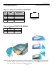
The DS9490R and DS9490B consume 58mA in USB active mode and 0.5mA in suspend mode*. The
DS9490R has the V
BUS
power and ground available on the RJ11 connector. In active mode the current
available to an externally powered fixture is 42mA* (100mA to 58mA); however it is recommended that
no more than 25mA be used. An external circuit can detect when the module is in suspend by monitoring
the SUSO signal on Pin 5 of the RJ11 connector. When this condition is detected, the external circuit must
also go into a low power state. NOTE: The SUSO pin of the DS2490 is an open drain output and requires
a pullup resistor to create a valid signal. See the DS2490 data sheet for the conditions where SUSO is
active. Revision C of the DS9490R and all revisions of the DS9490R# have SUSO routed to the RJ11
connector. The availability of SUSO at the RJ11 connector is not production tested. Therefore, before
relying on SUSO in an application, first verify the presence of this signal with the particular adapter.
*Guaranteed by design, not production tested.
**Tested at DS2490 component level.
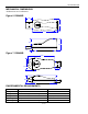
Figure 8. FUNCTIONAL DIAGRAM
EMI Filter
VBUS
D-
D+
GND
VIN VOUT
EN
N/C
GND
LP2980IM5-3.3
PMOD VD
NC NC
NC NC
NC NC
VB X1
SUSO X0
D- NC
D+ VPP
NC NC
OW NC
NC NC
GND NC
DS2490
C2
1.0uF
EMI Filter
C3
4.7
R2 24
R3 24
R1
1.5K
C1
0.1uF
OW
GND
DS2401
OW
GND
DS9503
USB
Connector
C6
33pF
C5
33pF
X1
12Mhz
L1
L2
C7
33pF
C8
33pF
U1
U2
U3
U4
J2
1
2
1
2
J1
1
2
3
4
1
3
4
5
2
1
5
7
8
12
24
19
20
17
10
1
2
3
4
5
6
Female RJ11
DS9490R
DS9490B
1
2
iButton Socket
J3
6
5
3
1
R7 10
5 of 6
DS9490R/DS9490B