
Datasheet


Evaluate: MAX11008
Quick Start
Required Equipment
• Maxim MAX11008EVC16 (contains MAX11008EVKIT+
board, HSI2CMOD, and 68HC16MODULE-DIP)
• DC power supply, 8V at 500mA
• DC power supply, 10V at 1000mA
• Windows 98/2000/XP computer with a spare serial
(COM) port
• 9-pin I/O extension cable
Note: In the following sections, software-related items
are identified by bolding. Text in bold refers to items
directly from the EV kit software. Text in bold and under-
lined refers to items from the Windows operating system.
Procedure
The MAX11008 EV kit is fully assembled and tested.
Follow the steps below to verify board operation. Caution:
Do not turn on the power until all connections are
completed.
1) Ensure that the MAX11008EVKIT jumpers are set in
accordance with Table 1.
2) Carefully connect the boards by aligning the 40-pin
header of the HSI2CMOD with the 40-pin connector of
the 68HC16MODULE-DIP module. Gently press them
together. The two boards should be flush against one
another. Next, connect the MAX11008 EVKIT 20-pin
connector to the HSI2CMOD board.
3) Connect the 8V DC power source to the
68HC16MODULE at the terminal block located next
to the on/off switch, along the top edge of the mod-
ule. Observe the polarity marked on the board.
4) Connect a cable from the computer’s serial port to
the 68HC16MODULE. If using a 9-pin serial port,
use a straight-through, 9-pin female-to-male cable.
If the only available serial port uses a 25-pin con-
nector, a standard 25-pin to 9-pin adapter is
required. The EV kit software checks the modem
status lines (CTS, DSR, DCD) to confirm that the
correct port has been selected.
5) Install the evaluation software on your computer by
launching MAX11008.msi. (The latest software can
be found at www.maxim-ic.com/evkitsoftware
.)
The program files are copied and icons are created
for them in the Windows Start
menu.
MAX11008 Evaluation Kit/
Evaluation System
2 _______________________________________________________________________________________
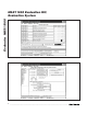
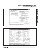
DESIGNATION QTY DESCRIPTION
R4 1 0Ω resistor (0603)
R5, R6 2 100Ω ±5% resistors (1206)
R7, R8 2
1.00Ω ±1% sense resistors (2010)
Vishay (Dale) CRCW20101R00FNEF
R10, R11 2 0Ω resistors (1206)
R12, R13 2 10kΩ ±5% resistors (1206)
R14, R15 2 47Ω ±5% resistors (1206)
U1 1
Dual RF LDMOS CODEC
(48 TQFN-EP*)
Maxim 11008BETM+
DESIGNATION QTY DESCRIPTION
U2 1
2.5V voltage reference (8 SO)
Maxim MAX6126AASA25+
U3 1
28V input linear regulator (5 SOT23)
Maxim MAX1615EUK+T
(Top Mark: ABZD)
— 21 Shunts
— 1 PCB: MAX11008 Evaluation Kit+
Component Suppliers
SUPPLIER PHONE WEBSITE
Fairchild Semiconductor 888-522-5372 www.fairchildsemi.com
International Rectifier 310-322-3331 www.irf.com
TDK Corp. 847-803-6100 www.component.tdk.com
Vishay 402-563-6866 www.vishay.com
Note: Indicate you are using the MAX11008 when contacting these component suppliers.
Component List (continued)
MAX11008EVKIT Component List (continued)
*
EP = Exposed pad.