
Datasheet
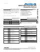


Evaluate: MAX11008
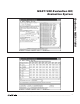
Tables Tab (Figure 4)
There are four look-up tables (LUTs) that can be loaded:
TLUT1 and TLUT2 for temperature compensation, and
ALUT1 and ALUT2 for optional additional compensation.
The EV kit software includes an MS-Excel spreadsheet
file MAX11008_LUT_Example.xls, which models how
physical temperature and voltage parameters can be
mapped into the MAX11008’s EEPROM memory. Refer
to the
Temperature/APC Configuration Registers
section
in the MAX11008 IC data sheet for detailed operation of
the look-up tables.
A set of radio buttons selects one of the four LUT con-
figuration registers. After clicking the appropriate radio
button for TLUT1, ALUT1, TLUT2, or ALUT2, the soft-
ware displays configuration values (pointer offset, linear
interpolation, pointer size, table size, and start of table).
After modifying any of these configuration values, click
the Apply Changes button to write the new configura-
tion value for the selected table.
To initialize a table, click the radio button selecting the
desired table. Enter the value 0 into the edit field next to
the Fill with constant button, then click to fill the table
with zeros. Enter the known correction values into the
table from the EEPROM tab, or click Load from file to
load the table points from a text file. Finally, click
Interpolate entries that contain zero to perform linear
interpolation on all zero value table entries. (This opera-
tion is not the same as the MAX11008’s linear interpola-
tion
between
table entries. The GUI software interpola-
tion fills in
missing
table entries.)
The memory map display shows which address range
is assigned to each enabled look-up table. Two or more
look-up tables may be assigned to the same address
range; however, they will contain identical data.
Overlapping table ranges are not recommended.
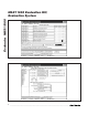
Alarms Tab (Figure 5)
The Alarms tab configures the ALARM output pin, tem-
perature and current alarm limits, hysteresis, and alarm
behavior.
ADC / Control Tab (Figure 6)
The ADC / Control tab configures the system parameters,
reads ADC data, and controls the gate-driver outputs.
Keyboard Navigation
When you type on the keyboard, the system must know
which control should receive the keys. Press the Tab
key to move the keyboard’s focus from one control to
the next. The focused control is indicated by a dotted
outline. Shift+Tab moves the focus to the previously
focused control. Buttons respond to the keyboard’s
SPACE bar. Some controls respond to the keyboard’s
UP and DOWN arrow keys. Activate the program’s
menu bar by pressing the F10 key, then press the letter
of the menu item you want. Most menu items have one
letter underlined, indicating their shortcut key.
Detailed Description of Hardware
For the purpose of “table-top” demonstration, two MOSFETS
(M1 and M2) are provided on-board, taking the place of
the LDMOS FETs that would be used in a real application.
Diode-connected BJT transistors D1 and D2 sense the
temperature of each FET while remaining electrically iso-
lated by different PCB copper layers. Capacitors C20 and
C21 filter the external temperature measurements. Gate
drive is lowpass filtered by R14/C28 and R15/C29. Drain
current is measured by Kelvin-connected precision resis-
tors R7 and R8, filtered by R5/C22 and R6/C23. Drain volt-
age is sensed by 6:1 resistor-dividers R9/R1 and R3/R3.
Power is provided from the HSI2CMOD board connect-
ed to J1. The digital supply connects directly to 5V
through jumper JU8. On-board MAX1615 regulator U3
provides the 5V analog supply through jumper JU12.
On-board MAX6126 voltage reference U2 drives both
REFADC and REFDAC through jumpers JU5 and JU6.
The MAX11008 power is bypassed by C4, C5, and
C24–C27.
The complete evaluation system is a three-board set,
with the 68HC16 microcontroller driving the HSI2CMOD
board’s high-speed I
2
C interface core. Refer to the
HSI2CMOD online documentation for details.
MAX11008 Evaluation Kit/
Evaluation System
4 _______________________________________________________________________________________