
Datasheet


Maxim Integrated
│
2
www.maximintegrated.com
Evaluates: MAX11300
MAX11300 Evaluation Kit
5) Connect the +12.5V DC power supply between
AVDDIO (+) and GND (-). Connect the -12.5V DC
power supply between AVSSIO (-) and GND (+).
6) Connect the DVM- to GND (-)
7) Enable the power-supply output.
8) Connect the USB cable from the PC to the EV kit
board. A Windows message appears when connect-
ing the EV kit board to the PC for the first time. Each
version of Windows has a slightly different message.
If you see a Windows message stating Ready to
Use, proceed to the next step. Otherwise, open the
USB_Driver_Help_200.PDF document in the Win-
dows Start | Programs menu to verify that the USB
driver was installed successfully.
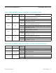
9) Use the DVM+ to verify the test point voltages shown
in Table 2.
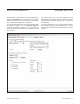
10) Start the MAX11300 Configuration Software by open-
ing its icon in the Windows Start | Programs menu.
The MAX11300 configuration software main window
appears, as shown in Figure 1. Drag and drop com-
ponents into the device, wire them up, and then use
the File menu | Generate Registers to export the
configuration to Max11300Register.csv.
11) Start the EV kit software by opening its icon in the
Windows Start | Programs menu. The EV kit soft-
ware main window appears, as shown in Figure 2.
12) Select File menu | Load Configuration... |
MAX11300Register.csv to load the configuration
into the MAX11300. Alternatively, use one of the
prebuilt demo configurations, such as MAX11300Reg-
ister_20131115_1505.csv, which configures all 20
PIXI ports with different configurations.
13) Select the Chart tab, then check Options menu |
Polling to show the analog inputs on a graph. Select
the Data tab to see the low-level input code values in
hexadecimal.
Figure 1. MAX11300 EV Kit Configuration Software
Figure 1