
Datasheet


Maxim Integrated
│
8
www.maximintegrated.com
Evaluates: MAX11300
MAX11300 Evaluation Kit
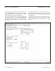
Detailed Description of Hardware
The MAX11300 EV kit uses an on-board MAXQ2000
microcontroller (U120) to send SPI commands to the
device. On-board level translators (U101, U102, and
U105) convert from 3.3V to 5V levels. On-board MAX6071
voltage references (U3, U6) provide ADC and DAC
reference voltages. Remote temperature sensing can be
simulated by on-board 3904 npn transistors (D0, D1). See
Figure 7.
Connecting to User-Supplied Circuitry
The EV kit connects to external, user-supplied circuitry
through header J1 or J2. These two headers have the
same signals; J1 is for vertical 50-pin ribbon-cable con-
nection and J2 is for right-angle connection to a sideboard
by standard 0.100in right-angle pins.
If remote temperature sensing is used, disconnect on-
board npn transistors D0 and D1 by moving the shunts of
JUD0P, JUD0N, JUD1P, and J1D1N to the 1-4 position.
Figure 7. MAX11300 EV Kit Hardware Overview
Figure 7
U1
MAX11300
20 PIXI PORTS
U4
MAX6389
SUPERVISOR
U7
MAX8511
2.5V LDO
U2
MAX8511
3.3V LDO
U200 FT232H
USB BRIDGE
U120
MAXQ2000
RUNNING MINIQUSB
FIRMWARE 01.05.50
HANDLES SPI/I
2
C/
GPIO COMMANDS
U101, U102
SPI LEVEL
TRANSLATORS
U8
MAX1659
5.0V LDO
U6
MAX6071
2.5V REFERENCE
U3
MAX6071
2.5V REFERENCE
CONNECTOR J1 or J2
TO CUSTOM
EXTERNAL
CIRCUITRY OR DEMO
BOARD
U105
MAX14595
I
2
C LEVEL
TRANSLATORS (NOT
INSTALLED)
EXTERNAL AVDDIO, AVSSIO
SUPPLIES
D0
3904 NPN TRANSISTOR
D1
3904 NPN TRANSISTOR
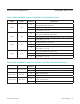
Table 1. Jumper Configuration (Power Supply)
JUMPER SIGNAL
SHUNT
POSITION
DESCRIPTION
JU_AVSSIO_GND AVSSIO
No Shunt* AVSSIO must be supplied by user negative power supply
1-2 AVSSIO = GND
JU_DVDD DVDD
1-2* DVDD is supplied from MAX1659 +5V LDO powered from AVDDIO
2-3 DVDD is supplied from USB
No Shunt DVDD must be supplied by user power supply
JU_AVDD AVDD
1-2* AVDD is supplied from DVDD directly
2-3 AVDD is supplied from DVDD, ltered by RAVDD and CAVDD
No Shunt AVDD must be supplied by user power supply