
Datasheet


Maxim Integrated
│
9
www.maximintegrated.com
Evaluates: MAX11300
MAX11300 Evaluation Kit
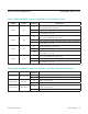
Table 1. Jumper Configuration (Power Supply) (continued)
Table 2. Jumper Configuration (Digital Interface)
*Default position.
**Default connection by a trace on the PCB; jumper pins not installed; shunt not included.
*Default position.
**Default connection by a trace on the PCB; jumper pins not installed; shunt not included.
JUMPER SIGNAL
SHUNT
POSITION
DESCRIPTION
JU_SDA_DIN SDA_DIN
1-2** SDA_DIN = MAXQ_MOSI (SPI interface mode)
2-3 SDA_DIN = MAXQ_SDA (reserved)
No Shunt SDA_DIN = User-supplied connection
JU_SDA SDA
1-2 SDA pullup to DVDD by R103 (reserved)
No Shunt* R103 is not connected (SPI interface mode)
JU_SCL_SCLK SCL_SCLK
1-2** SCL_SCLK = MAXQ_SCLK (SPI interface mode)
2-3 SCL_SCLK = MAXQ_SCL (reserved)
No Shunt SCL_SCLK = User-supplied connection
JU_SCL SCL
1-2 SCL pullup to DVDD by R104 (reserved)
No Shunt* R104 is not connected (SPI interface mode)
JU_AD0_CSB AD0/CSB
1-2** AD0/CSB = MAXQ_CS (SPI interface mode)
3-4 AD0/CSB = DVDD (reserved)
5-6 AD0/CSB = SCL_SCLK (reserved)
7-8 AD0/CSB = SDA_DIN (reserved)
9-10 AD0/CSB = DGND. (reserved)
JU_AD1_DOUT AD1/DOUT
1-2 AD1/DOUT = DGND (reserved)
1-3** AD1/DOUT = MAXQ_MOSI.(SPI interface mode)
1-4 AD1/DOUT = DVDD (reserved)
JU_INTB INTB
1-2** INTB = MAXQ_K5 interrupt input to microcontroller
Open INTB = user-supplied connection
JU_CNVTB CNVTB
1-2** CNVTB = MAXQ_K4 output from microcontroller
Open CNVTB = user-supplied connection
JUMPER SIGNAL
SHUNT
POSITION
DESCRIPTION
JU_U1_AVDDIO AVDDIO 1-2**
Measure the supply current by putting a current meter in series with
the jumper.
JU_U1_AVSSIO AVSSIO 1-2**
Measure the supply current by putting a current meter in series with
the jumper.
JU_U1_AVDD AVDD 1-2**
Measure the supply current by putting a current meter in series with
the jumper.
JU_U1_DVDD DVDD 1-2**
Measure the supply current by putting a current meter in series with
the jumper.