
Datasheet


Maxim Integrated
│
2
www.maximintegrated.com
Evaluates: MAX11300
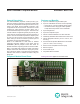
MAX11300PMB1 Peripheral Module
Detailed Description
SPI Interface
The MAX11300PMB1 Pmod can plug directly into a
Pmod-compatible port (configured for SPI) through the
X1 connector. For information on the SPI protocol, refer
to the MAX11300 IC data sheet.
● Connector X1 provides connection of the module to
the Pmod host. See Table 1 and Figure 1 for detailed
description.
● Connectors SV1 and SV2 provide connection to the
IC pins (MAX11300 ports 0–19). Connector SV3 is
ground.
● Connectors EXT_TEMP1 and EXT_TEMP2 provide
connection to the external temperature sensors.
● Connector VDDIO provides connection to the
AVDDIO pins of the device, which is connected to
the +12V power supply
● Connector VSSIO provides connection to the
AVSSIO pins of the device, which is the analog
negative supply for mixed-signal ports. Install the
VSSIO jumper to connect AVSSIO to ground.
Figure 1. X1: Pmod SPI Connector Pin Configuration
7
10
8
9
11
12
1
4
2
3
5
6
X1
SPI
CS
MOSI
MISO
SCLK
GND
3.3V3.3V
.
GND
CNVTB
INTB
PIN SIGNAL DESCRIPTION
1 CS Chip Select. Assert low to enable the SPI interface.
2 MOSI MAX11300 Serial Data Input
3 MISO MAX11300 Serial-Data Output
4 SCLK MAX11300 Serial-Clock Input
5, 11 GND Ground
6, 12 +3.3V +3.3V Power Supplies
7 INTB Interrupt Open-Drain Output. Asserted low when the MAX11300 issues an interrupt.
8 — No Connection
9 — No Connection
10 CNVTB ADC Conversion Control Input. Assert low to initiate an ADC conversion.
Table 1. Connector X1 (SPI Communication)