
Datasheet


MAX1270 EV Kit/EV System
_______________________________________________________________________________________ 5
Evaluates: MAX1270/MAX1271/MAX127/MAX128
Average value is the arithmetic mean; i.e., the sum of all
values divided by the number of samples. Standard
deviation is used as an approximation to RMS voltage.
Device Characteristics
The Device Characteristics dialog box is used to select
between the MAX1270 and MAX1271.
Evaluating the MAX1271
The MAX1270 software can evaluate the MAX1271
directly. From the Window menu, pick Device
Characteristics. Next, change the device type from
MAX1270 to MAX1271 and click the Apply button. This
tells the program that the input voltage span is ±V
REF
instead of ±10V.
Changing the Reference Voltage
The MAX1270 EV kit software assumes a 4.096V refer-
ence voltage, unless otherwise specified by the user. To
use the on-board MAX6141 reference (V
REF
= 4.096V)
close JU2 and JU3. For an external, user-supplied refer-
ence, close JU2, open JU3, and apply the reference to
the V
REF
pad. To use the internal reference, open JU2
and JU3. See the MAX1270 data sheet for more infor-
mation. From the Window menu, select Device
Characteristics, then type the new reference voltage
into the Reference Voltage edit box.
Detailed Description
of Hardware
U1 is a MAX1270/MAX1271/MAX127/MAX128 analog-
to-digital converter. C10 bypasses the internal
bandgap reference, and C11 bypasses the 4.096 volt
reference output. Sockets U2 and U3 accommodate
optional unity-gain-stable quad op amp buffers. C2–C9
and R6–R13 form anti-aliasing input filters for the eight
input channels. U4 is an optional MAX6141 external ref-
erence. U5 is a linear regulator that provides +5V to U1
when used in stand-alone mode.
Measuring Supply Current
Supply current can be monitored by measuring the volt-
age across resistor R1. This resistor is 10Ω ±5%, so
every 1mV across R1 represents 100µA of supply cur-
rent.
Troubleshooting
Problem: No output measurement. System seems to
report zero voltage or fails to make a measurement.
• Check the +5V supply voltage. Check the buffer op-
amp supply voltages if applicable.
• Check the V
REF
and REFADJ reference voltages
using a digital voltmeter.
• Use an oscilloscope to verify that pin 5 (SCLK/SCL) is
receiving clock strobe pulses.
• Verify that SHDN is not being pulled low.
Problem: Erratic, unstable measurement. Use an
oscilloscope to measure:
• V
REF
—increase reference capacitor if necessary.
• SHDN—ensure that shutdown mode is not activated.
• Analog input (while triggering on DIN)—large voltage
disturbances can be cured by using an op amp
buffer (see Op Amp Buffers section).
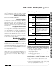
Table 2. Jumper Functions
Table 3. Voltage Reference Truth Table
JUMPER STATE FUNCTION
1-2
U1 = MAX127 or MAX128. Use 2-wire
interface signals on TP1 test points.
JU1
2-3*
U1 = MAX1270 or MAX1271. Use
3-wire interface signals on TP1 test
points, or use 68HC16 module and
supplied software.
Open
Enable U1’s internal reference. JU3
must be open.
JU2
Closed*
Disable U1’s internal reference. Refer to
Table 3, Voltage Reference Truth Table.
Open
If JU2 is open, selects internal
reference. If JU2 is closed, user must
provide reference at VREF input pad.
Refer to Table 3, Voltage Reference
Truth Table.
JU3
Closed*
Use voltage reference U4. Jumper JU2
must be closed.
JU2 JU3 FUNCTION
Open Open Enable U1’s internal reference
Open Closed Invalid operating configuration
Closed Open
User must provide a reference at the
Closed Closed Use voltage reference U4