
Datasheet


MAX13046E/MAX13047E
Single- and Dual-Bidirectional
Low-Level Translator
_______________________________________________________________________________________ 5
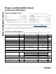
TIMING CHARACTERISTICS FOR +1.8V ≤ V
L
≤ V
CC
≤ +3.3V
(+1.8V ≤ V
L
≤ V
CC
≤ +3.3V, R
S
= 50Ω, R
L
= 1MΩ, C
L
= 15pF, T
A
= -40°C to +85°C, unless otherwise noted. Typical values are V
CC
= +3.3V,
V
L
= +1.8V at T
A
= +25°C.) (Notes 2, 3, 5)
PARAMETER
SYMBOL
CONDITIONS
MIN TYP MAX UNITS
I/O V
CC
Rise Time t
RVCC
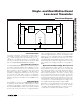
Push-pull driving, Figure 1a 15 ns
I/O V
CC
Fall Time t
FVCC
Push-pull driving, Figure 1a 15 ns
I/O V
L
Rise Time t
RVL
Push-pull driving, Figure 1b 15 ns
I/O V
L
Fall Time t
FVL
Push-pull driving, Figure 1b 15 ns
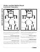
t
PD-VL-VCC
Push-pull driving, driving I/O V
L
15
Propagation Delay
t
PD-VCC-VL
Push-pull driving, driving I/O V
CC
15
ns
Channel-to-Channel Skew t
SKEW
Push-pull driving, each translator
equally loaded
10 ns
Maximum Data Rate Push-pull driving 16
Mbps
Note 2: All units are 100% production tested at T
A
= +25°C. Limits over the operating temperature range are guaranteed by design
and not production tested.
Note 3: For normal operation, ensure V
L
< (V
CC
+ 0.3V). During power-up, V
L
> (V
CC
+ 0.3V) does not damage the device.
Note 4: ESD protection is guaranteed by design. To ensure maximum ESD protection, place a 1µF ceramic capacitor between V
CC
and GND. See
Typical Application Circuits
.
Note 5: Timing is measured using 10% of input to 90% of output.