
Datasheet


4 Maxim Integrated
Adjustable Overvoltage and Overcurrent
Protectors with High Accuracy
MAX14571/MAX14572/MAX14573
ELECTRICAL CHARACTERISTICS (continued)
(V
IN
= 4.5V to 36V, T
A
= -40NC to +85NC, unless otherwise noted. Typical values are at V
IN
= 24V, R
ISET
. = 12kI, T
A
= +25°C.) (Note 3)
Note 3: All units are 100% production tested at T
A
= +25NC. Limits over the operating temperature range are guaranteed by
design and characterization; not production tested.
Note 4: Not production tested, user settable. See overvoltage/undervoltage lockout instructions.
Note 5: Guaranteed by design; not production tested. UVLO and OVLO are internally clamped to BG reference voltage.
Note 6: The current limit can be set below 700mA with a decreased accuracy.
Note 7: All timing is measured using 20% and 80% levels.
Note 8: The ratio between the autoretry time and blanking time is fixed and equal to 30.
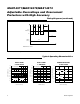
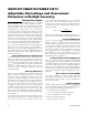
Timing Diagrams
Figure 1. Autoretry Fault Diagram
t
BLANK
t
BLANK
t
BLANK
t
BLANK
t
RETRY
t
RETRY
t
RETRY
NOTE:
TIME NOT IN SCALE
AUTORETRY VERSIONS
OUT
CURRENT LIMIT
LOAD CURRENT
FLAG
THE DEVICE GOES
TO THERMAL
SHUTDOWN MODE
THE DEVICE COMES
OUT OF THERMAL
SHUTDOWN MODE
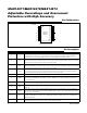
PARAMETER SYMBOL CONDITIONS MIN TYP MAX UNITS
ESD PROTECTION
IN
Human Body Model, IN bypassed
to GND with a 1FF low-ESR ceramic
capacitor
Q15
kV