
Datasheet


MAX14588 1A Adjustable Overcurrent and Overvoltage
Protector with High Accuracy
www.maximintegrated.com
Maxim Integrated
│
9
Pin Description
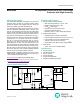
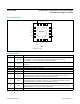
Pin Conguration
PIN NAME FUNCTION
1 CLTS_MODE
Current-Limit-Type Select Mode.
CLTS_MODE = 0: CLTS1 and CLTS2 are sampled only when (V
IN
– V
OUT
) < 0.6V.
CLTS_MODE = 1: CLTS1 and CLTS2 are continuously sampled.
2 CLHS
Current-Limit-Type-Select Logic-High Voltage. Connect CLTS_MODE/CLTS1/CLTS2 to CLHS for
logic-high.
3 CLTS1 Current-Limit-Type Select 1. See Table 1.
4 CLTS2 Current-Limit-Type Select 2. See Table 1.
5 HVEN 36V Capable Active-Low Enable Input. See Table 2.
6, 7 IN Overvoltage Protection Input. Bypass IN to ground with a 0.47µF ceramic capacitor.
8 OVLO
Externally Programmable Overvoltage Lockout Threshold. Connect OVLO to GND to use the
default internal OVLO threshold. Connect OVLO to an external resistor-divider to dene a
threshold externally and override the preset internal OVLO threshold.
9 UVLO
Externally Programmable Undervoltage Lockout Threshold. Connect UVLO to GND to use
the default internal UVLO threshold. Connect UVLO to an external resistor-divider to dene a
threshold externally and override the preset internal UVLO threshold.
10 SETI
Overload-Current-Limit Adjust. Connect a resistor from SETI to GND to program the overcurrent
limit. SETI must be connected to a resistor. If SETI is connected to GND, the FETs turn off and
FLAG is asserted. Do not connect more than 10pF to SETI.
11 GND Ground
15
16
14
13
6
5
7
CLHS
CLTS2
8
CLTS_MODE
GND
UVLO
FLAG
12
OUT
4
12 11 9
OUT
*EP
RIEN
OVLO
IN
IN
HVEN
*CONNECT EP TO GND
+
CLTS1 SETI
3
10
EN
TQFN
MAX14588
TOP VIEW