
Datasheet

MAX1570
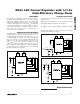
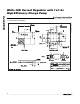
White LED Current Regulator with 1x/1.5x
High-Efficiency Charge Pump
6 _______________________________________________________________________________________
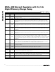
Pin Description
PIN NAME FUNCTION
1 C1P Transfer Capacitor 1 Positive Connection
2 EN2
Enable, Dimming Control Input 2. EN2 and EN1 control shutdown, 1/3 current, 2/3 current, and full
current (see Table1).
3 GND Analog Ground. Connect directly to the exposed paddle underneath the IC.
4 LED5
LED5 Cathode Connection. Current flowing into LED5 is 230 times the current flowing out of SET.
When using fewer than five LEDs, this pin can be left unconnected. LED5 is high impedance during
shutdown.
5 LED4
LED4 Cathode Connection. Current flowing into LED4 is 230 times the current flowing out of SET.
When using fewer than five LEDs, this pin can be left unconnected. LED4 is high impedance during
shutdown.
6 LED3
LED3 Cathode Connection. Current flowing into LED3 is 230 times the current flowing out of SET.
When using fewer than five LEDs, this pin can be left unconnected. LED3 is high impedance during
shutdown.
7 LED2
LED2 Cathode Connection. Current flowing into LED2 is 230 times the current flowing out of SET.
When using fewer than five LEDs, this pin can be left unconnected. LED2 is high impedance during
shutdown.
8 LED1
LED1 Cathode Connection and Charge-Pump Feedback. Current flowing into LED1 is 230 times the
current flowing out of SET. The charge pump regulates the voltage on LED1 to various voltages
depending upon the status of EN1 and EN2 (see Table 1). Grounding LED1 forces OUT to operate at
5V while LED2–LED5 regulate the LED current to 230 x V
SET
/R
SET
. LED1 is high impedance during
shutdown.
9 SET
Bias Current Set Input. The current flowing out of SET programs the bias current into each LED by
I
LED_
= 230 x I
SET
. V
SET
is internally biased to various voltages (see Table 1). Connect a resistor to
GND to set the bias current as V
SET
/R
SET
. SET is high impedance during shutdown.
10 EN1
Enable, Dimming Control Input 1. EN1 and EN2 control shutdown, 1/3 current, 2/3 current, and full
current (see Table 1).
11 PGND
Power Ground. Charge-pump switching current flows through this pin. Connect to GND and system
ground as close to the MAX1570 and the input bypass capacitor as possible.
12 C1N Transfer Capacitor 1 Negative Connection
13 IN
Supply Voltage Input. Bypass IN to PGND with a 1µF ceramic capacitor. The input voltage range is
2.7V to 5.5V. IN is high impedance during shutdown.
14 C2P Transfer Capacitor 2 Positive Connection
15 OUT
Charge-Pump Output. Bypass to PGND with a 4.7µF ceramic capacitor as close to the IC as possible.
Connect to the anodes of all the LEDs. OUT is high impedance during shutdown.
16 C2N Transfer Capacitor 2 Negative Connection
—EPExposed paddle. Connect to GND.