
Datasheet

MAX16025–MAX16030
Applications Information
Tolerance
The MAX16025–MAX16030 feature a pin-selectable
threshold tolerance. Connect TOL to GND to select the
thresholds 5% below the nominal value. Connect TOL to
V
CC
to select the threshold tolerance 10% below the
nominal voltage. Do not leave TOL unconnected.
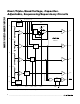
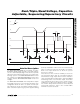
Adjustable Input
These devices offer several monitoring options with
both fixed and/or adjustable reset thresholds (see
Table 2). For the adjustable threshold inputs, the
threshold voltage (V
TH
) at each adjustable IN_ input is
typically 0.5V (TOL = GND) or 0.472V (TOL = V
CC
). To
monitor a voltage V
INTH
, connect a resistive divider net-
work to the circuit as shown in Figure 3 and use the fol-
lowing equation to calculate the threshold voltage:
Choosing the proper external resistors is a balance
between accuracy and power use. The input to the volt-
age monitor is a high-impedance input with a small
100nA leakage current. This leakage current con-
tributes to the overall error of the threshold voltage
where the output is asserted. This induced error is pro-
portional to the value of the resistors used to set the
threshold. With lower value resistors, this error is
reduced, but the amount of power consumed in the
resistors increases.
The following equation is provided to help estimate the
value of the resistors based on the amount of accept-
able error:
where e
A
is the fraction of the maximum acceptable
absolute resistive divider error attributable to the input
leakage current (use 0.01 for ±1%), V
INTH
is the volt-
age at which the output (OUT_) should assert, and I
L
is
the worst-case IN_ leakage current (see the
Electrical
Characteristics
). Calculate R2 as follows:
Unused Inputs
Connect any unused IN_ and EN_ inputs to V
CC
.
OUT_ Output
An OUT_ goes low when its respective IN_ input voltage
drops below its specified threshold or when its EN_ goes
low (see Table 1). OUT_ goes high when EN_ is high and
V
IN_
is above its threshold after a time delay. The
MAX16025/MAX16027/MAX16029 feature open-drain,
outputs while the MAX16026/MAX16028/MAX16030
have push-pull outputs. Open-drain outputs require an
external pullup resistor to any voltage from 0 to 28V.
RESET
Output
RESET asserts low when any of the monitored voltages
(IN_) falls below its respective threshold, any EN_ goes
low, or MR is asserted. RESET remains asserted for the
reset timeout period after all of the monitored voltages
exceed their respective threshold, all EN_ are high, all
OUT_ are high, and MR is deasserted. The MAX16025/
MAX16027/MAX16029 have an open-drain, active-low
reset output, while the MAX16026/MAX16028/
MAX16030 have a push-pull, active-low reset output.
Open-drain RESET requires an external pullup resistor to
any voltage from 0 to 28V.
Adjustable Reset Timeout Period
(CRESET)
All of these parts offer an internally fixed reset timeout
(140ms min) by connecting CRESET to V
CC
. The reset
timeout can also be adjusted by connecting a capaci-
tor from CRESET to GND. When the voltage at CRESET
reaches 0.5V, RESET goes high. When RESET goes
high, CRESET is immediately held low.
R
VR
VV
TH
INTH TH
2
1
=
×
−
R
eV
I
A INTH
L
1
=
×
VV
R
R
INTH TH
=×+
⎛
⎝
⎜
⎞
⎠
⎟
1
1
2
Dual-/Triple-/Quad-Voltage, Capacitor-
Adjustable, Sequencing/Supervisory Circuits
10 ______________________________________________________________________________________
IN_
V
TH
V
INTH
R1 = R2 x
(
)
V
INTH
V
TH
R1
R2
MAX16025–
MAX16030
-1
Figure 3. Setting the Adjustable Input