
Datasheet

MAX16025–MAX16030
Dual-/Triple-/Quad-Voltage, Capacitor-
Adjustable, Sequencing/Supervisory Circuits
6 _______________________________________________________________________________________
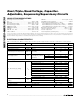
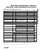
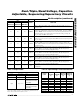
Pin Description
PIN
MAX16025/
MAX16026
MAX16027/
MAX16028
MAX16029/
MAX16030
NAME FUNCTION
111V
CC
Supply Voltage Input. Connect a 2.2V to 28V supply voltage to power the
device. All outputs are low when V
CC
is below the UVLO. For noisy systems,
bypass V
CC
to GND with a 0.1µF capacitor.
2 2 2 IN1
Monitored Input 1. When the voltage at IN1 exceeds its threshold, OUT1 goes
high after the capacitor-adjustable delay period. When the voltage at IN1 falls
below its threshold, OUT1 goes low after a propagation delay.
3 3 3 IN2
Monitored Input 2. When the voltage at IN2 exceeds its threshold, OUT2 goes
high after the capacitor-adjustable delay period. When the voltage at IN2 falls
below its threshold, OUT2 goes low after a propagation delay.
— 4 4 IN3
Monitored Input 3. When the voltage at IN3 exceeds its threshold, OUT3 goes
high after the capacitor-adjustable delay period. When the voltage at IN3 falls
below its threshold, OUT3 goes low after a propagation delay.
— — 5 IN4
Monitored Input 4. When the voltage at IN4 exceeds its threshold, OUT4 goes
high after the capacitor-adjustable delay period. When the voltage at IN4 falls
below its threshold, OUT4 goes low after a propagation delay.
4 5 6 TOL
Threshold Tolerance Input. Connect TOL to GND to select thresholds 5%
below nominal. Connect TOL to V
CC
to select thresholds 10% below nominal.
5 6 7 GND Ground
6 7 8 EN1
Active-High Logic-Enable Input 1. Driving EN1 low causes OUT1 to go low
regardless of the input voltage. Drive EN1 high to enable the monitoring
comparator.
7 8 9 EN2
Active-High Logic-Enable Input 2. Driving EN2 low causes OUT2 to go low
regardless of the input voltage. Drive EN2 high to enable the monitoring
comparator.
— 9 10 EN3
Active-High Logic-Enable Input 3. Driving EN3 low causes OUT3 to go low
regardless of the input voltage. Drive EN3 high to enable the monitoring
comparator.
— — 11 EN4
Active-High Logic-Enable Input 4. Driving EN4 low causes OUT4 to go low
regardless of the input voltage. Drive EN4 high to enable the monitoring
comparator.
8 10 12 TH1
Threshold Select Input 1. Connect TH1 to V
CC
or GND, or leave it open to
select the input-voltage threshold option in conjunction with TH0 (see Table 2).
9 11 13 TH0
Threshold Select Input 0. Connect TH0 to V
CC
or GND, or leave it open to
select the input-voltage threshold option in conjunction with TH1 (see Table 2).
— — 14 OUT4
Output 4. When the voltage at IN4 is below its threshold or EN4 goes low,
OUT4 goes low.
— 12 15 OUT3
Output 3. When the voltage at IN3 is below its threshold or EN3 goes low,
OUT3 goes low.
10 13 16 OUT2
Output 2. When the voltage at IN2 is below its threshold or EN2 goes low,
OUT2 goes low.