
Datasheet

Detailed Description
The MAX1722/MAX1723/MAX1724 compact, high-effi-
ciency, step-up DC-DC converters are guaranteed to
start up with voltages as low as 0.91V and operate with
an input voltage down to 0.8V. Consuming only 1.5μA of
quiescent current, these devices include a built-in syn-
chronous rectifier that reduces cost by eliminating the
need for an external diode and improves overall efficiency
by minimizing losses in the circuit (see Synchronous
Rectification section). The MAX1722/MAX1724 feature
a clamp circuit that reduces EMI due to inductor ringing.
The MAX1723/MAX1724 feature an active-low shutdown
that reduces quiescent supply current to 0.1μA. The
MAX1722/MAX1723 have an adjustable output voltage,
while the MAX1724 is available with four fixed-output
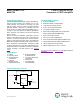
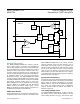
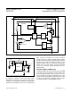
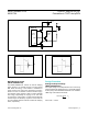
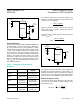
voltage options (see Selector Guide). Figure 1 is the
MAX1723 simplified functional diagram and Figure 2 is
the MAX1724 simplified functional diagram.
PFM Control Scheme
A forced discontinuous, current-limited, pulse-frequency-
modulation (PFM) control scheme is a key feature of the
MAX1722/MAX1723/MAX1724. This scheme provides
ultra-low quiescent current and high efficiency over a
wide output current range. There is no oscillator; the
inductor current is limited by the 0.5A N-channel current
limit or by the 5μs switch maximum on-time. Following
each on cycle, the inductor current must ramp to zero
before another cycle may start. When the error compara-
tor senses that the output has fallen below the regulation
threshold, another cycle begins.
Synchronous Rectication
The internal synchronous rectifier eliminates the need for
an external Schottky diode, thus reducing cost and board
space. While the inductor discharges, the P-channel
MOSFET turns on and shunts the MOSFET body diode.
As a result, the rectifier voltage drop is significantly
reduced, improving efficiency without the addition of
external components.
Low-Voltage Startup Circuit
The MAX1722/MAX1723/MAX1724 contain a low-volt-
age startup circuit to control DC-DC operation until the
output voltage exceeds 1.5V (typ). The minimum start-
Figure 1. MAX1723 Simplified Functional Diagram
P
N
CONTROL
LOGIC
STARTUP
CIRCUITRY
DRIVER
GND
FB
OUT
LX
CURRENT
LIMIT
1.235V REFERENCE
ERROR
COMPARATOR
ZERO-
CROSSING
DETECTOR
MAX1723
SHDN
MAX1722/MAX1723/
MAX1724
1.5μA I
Q
, Step-Up DC-DC
Converters in TSOT and µDFN
www.maximintegrated.com
Maxim Integrated
│
7