
Datasheet


Table Of Contents
- General Description
- Features
- Component List
- Component Suppliers
- Quick Start
- Detailed Description of Hardware
- Ordering Information
- Revision History
- LIST OF FIGURES
- Figure 1. MAX17502F Load and Line Regulation
- Figure 2. MAX17502F Efficiency
- Figure 3. MAX17502F Full Load Bode Plot (VIN = 24V)
- Figure 5. MAX17502F 250mA to 500mA Load Transient
- Figure 4. MAX17502F No Load to 250mA Load Transient
- Figure 6. MAX17502F EV Kit Schematic
- Figure 7. MAX17502F EV Kit Component Placement Guide—Component Side
- Figure 8. MAX17502F EV PCB Layout—Component Side
- Figure 9. MAX17502F EV Kit PCB Layout—Solder Side
- Figure 10. MAX17502F EV Kit PCB Layout—Top Solder Mask
- Figure 11. MAX17502F EV Kit PCB Layout—Bottom Solder Mask
- LIST OF TABLES
MAX17502F Evaluation Kit Evaluates: MAX17502F in TDFN Package
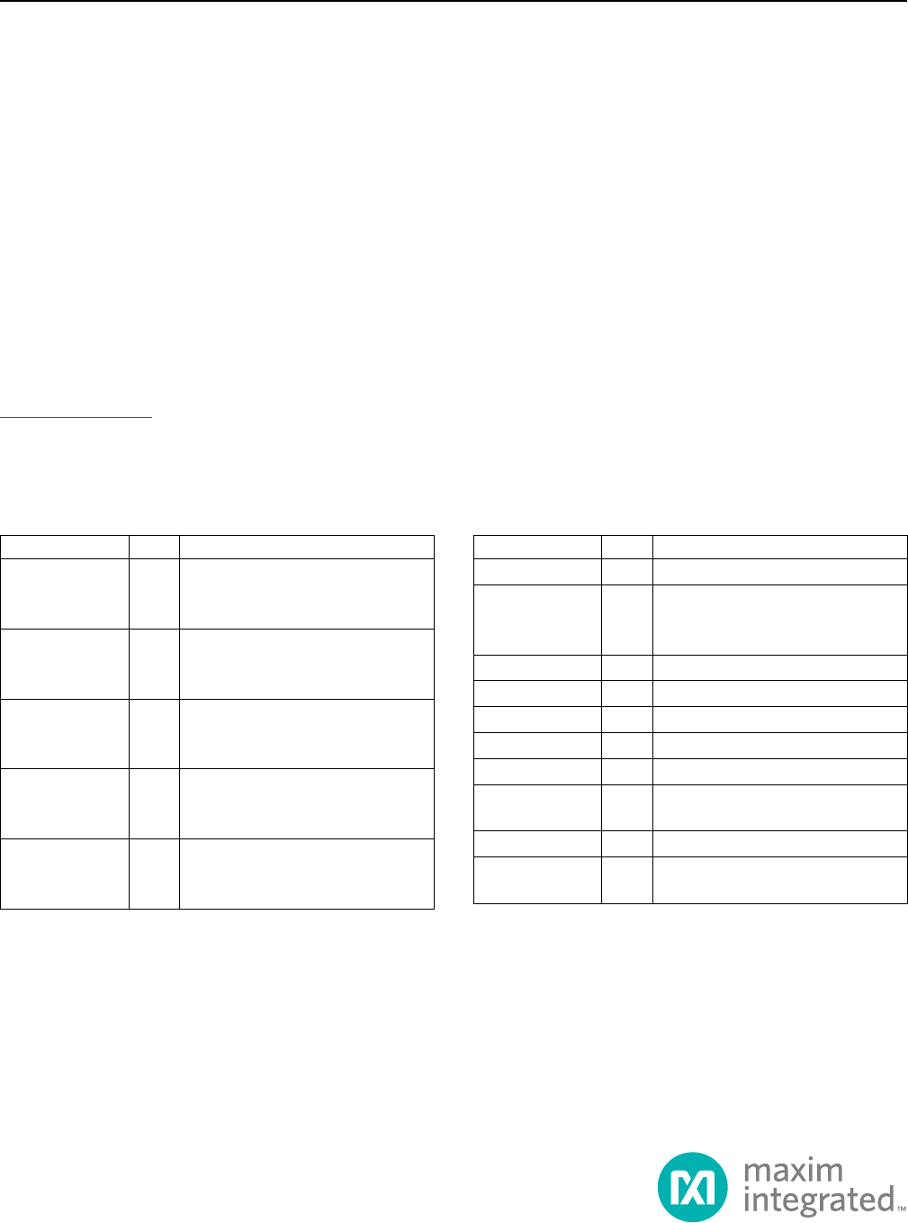
Component List
General Description
The MAX17502F evaluation kit (EV kit) provides a proven
design to evaluate the MAX17502F high-efficiency, high-
voltage, synchronous step-down DC-DC converter. The
EV kit uses the device to generate a fixed 5V at load cur-
rents up to 1A from a 7V to 60V input supply. The device
features a forced-PWM control scheme that provides
constant switching-frequency operation at all load and
line conditions.
Features
● Operatesfroma7Vto60VInputSupply
● 5VFixedOutputVoltage
● 1AOutputCurrent
● 600kHzSwitchingFrequency
● Enable/UVLOInput
● Resistor-ProgrammableUVLOThreshold
● Open-DrainRESETOutput
● OvercurrentandOvertemperatureProtection
● ProvenPCBLayout
● FullyAssembledandTested
19-6511; Rev 1; 10/13
Ordering Information appears at end of data sheet.
*EP = Exposed pad.
DESIGNATION QTY DESCRIPTION
C1 1
2.2µF±10%,100VX7Rceramic
capacitor (1210)
MurataGRM32ER72A225K
C2 1
1µF±10%,6.3VX7Rceramic
capacitor(0603)
MurataGRM188R70J105K
C3 1
3300pF±10%,50VX7Rceramic
capacitor (0402)
MurataGRM155R71H332K
C4 1
10µF±10%,10VX7Rceramic
capacitor (1210)
MurataGRM32DR71A106K
C7 1
33µF,80Valuminumelectrolytic
(D=8mm)
PanasonicEEEFK1K330P
DESIGNATION QTY DESCRIPTION
JU1 1
3-pinheader
L1 1
22µH,1.7Ainductor
(6mmx6mmx3.5mm)
CoilcraftLPS6235-223ML
R1 1 3.32MΩ±1%resistor(0402)
R2 1 866kΩ±1%resistor(0402)
R4 1 100Ωresistor(0402)
R6 1 10kΩ±1%resistor(0402)
TP1, TP2 0 Not installed, test points
U1 1
Buckconverter(10TDFN-EP*)
MaximMAX17502FATB+
— 1 Shunt
— 1
PCB:MAX17502FTEVALUATION
KIT