
Datasheet


Table Of Contents
- MAX17505 5V Output Evaluation Kit
- General Description
- Features
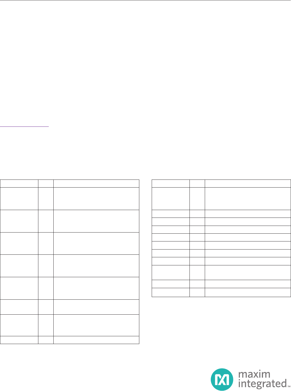
- Component List
- Component Suppliers
- Quick Start
- Recommended Equipment
- Procedure
- Detailed Description
- Soft-Start Input (SS)
- Regulator Enable/Undervoltage-Lockout Le
- INUR11.215R2(V1.215)×=−
- MODE Selection (MODE)
- External Clock Synchronization (SYNC)
- EV Kit Test Report
- Ordering Information
- Revision History
- LIST OF FIGURES
- Figure 1. MAX17505 5V Output Load and Li
- Figure 2. MAX17505 5V Output Efficiency
- Figure 3. MAX17505 5V Output Load and Li
- Figure 4. MAX17505 5V Output Efficiency
- Figure 5. MAX17505 5V Output Efficiency
- Figure 6. MAX17505 5V Output Full Load B
- Figure 7. MAX17505 5V Output, No Load to
- Figure 8. MAX17505 5V Output, 5mA to 0.8
- Figure 9. MAX17505 5V Output, 50mA to 0.
- Figure 10. MAX17505 5V Output, 0.85A to
- Figure 11. MAX17505 5V Output EV Kit Sch
- Figure 12. MAX17505 5V Output EV Kit Com
- Figure 13. MAX17505 5V Output EV Kit Com
- Figure 14. MAX17505 5V Output EV Kit PCB
- Figure 15. MAX17505 5V Output EV Kit PCB
- Figure 16. MAX17505 5V Output EV Kit PCB
- Figure 17. MAX17505 5V Output EV Kit Com
- Figure 18. MAX17505 5V Output EV Kit Com
- LIST OF TABLES
Evaluates: MAX17505 in
5V Output-Voltage Application
MAX17505 5V Output Evaluation Kit
General Description
The MAX17505 5V output evaluation kit (EV kit) provides
a proven design to evaluate the MAX17505 high-voltage,
high-efficiency, synchronous step-down DC-DC convert-
er. The EV kit is preset for 5V output at load currents up
to 1.7A and features a 500kHz switching frequency for
optimum efficiency and component size. The EV kit
features adjustable input undervoltage lockout, adjust-
able soft-start, open-drain RESET signal, and external
frequency synchronization.
Features
● Operates from a 6.5V to 60V Input Supply
● 5V Output Voltage
● Up to 1.7A Output Current
● 500kHz Switching Frequency
● Enable/UVLO Input, Resistor-Programmable UVLO
Threshold
● Adjustable Soft-Start Time
● MODE Pin to Select Among PWM, PFM, or DCM
Modes
● Open-Drain RESET Output
● External Frequency Synchronization
● Overcurrent and Overtemperature Protection
● Proven PCB Layout
● Fully Assembled and Tested
19-6899; Rev 0; 1/14
Ordering Information appears at end of data sheet.
*EP = Exposed pad.
Note: C7, R1, and R2 are optional components; R1 and R2 are
not needed if the EN/UVLO pin is permanently connected to
VIN. The electrolytic capacitor (C7) is required only when the
VIN power supply is situated far from the MAX17505-based
circuit. When R5 is open, the device switches at 500kHz
switching frequency. The XAL6060 inductor has been used to
prepare the EV kit test report.
DESIGNATION QTY DESCRIPTION
C1 1
2.2µF ±10%, 100V X7R ceramic
capacitor (1210)
Murata GRM32ER72A225KA35
C2 1
2.2µF ±10%, 10V X7R ceramic
capacitor (0603)
Murata GRM188R71A225K
C3 1
5600pF ±10%, 25V X7R ceramic
capacitor (0402)
Murata GRM155R71E562K
C4 1
22µF ±10%, 10V X7R ceramic
capacitor (1210)
Murata GRM32ER71A226K
C5 1
0.1µF ±10%, 16V X7R ceramic
capacitor (0402)
Murata GRM155R71C104K
C6 0
Not installed, ceramic capacitor
(0402)
C7 1
47µF, 80V aluminum electrolytic
capacitor (D = 10mm)
Panasonic EEEFK1K470P
JU1–JU3 3 3-pin headers
DESIGNATION QTY DESCRIPTION
L1 1
10μH inductor
Coilcraft XAL6060-103ME
Cooper Bussmann MPI4040R4-100-R
R1 1 3.32MΩ ±1% resistor (0402)
R2 1 732kΩ ±1% resistor (0402)
R3 1 178kΩ ±1% resistor (0402)
R4 1 39kΩ ±1% resistor (0402)
R5 0 Not installed, resistor (0402)
R6 1 10kΩ ±1% resistor (0402)
TP1, TP2 2 Test pads
U1 1
Buck converter (20 TQFN-EP*)
Maxim MAX17505ATP+
— 3 Shunts (JU1–JU3)
— 1 PCB: MAX17505 – 5V Output EVKIT
Component List