
Datasheet


MAX3013
+1.2V to +3.6V, 0.1µA, 100Mbps,
8-Channel Level Translators
2 _______________________________________________________________________________________
ABSOLUTE MAXIMUM RATINGS
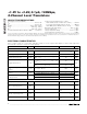
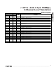
ELECTRICAL CHARACTERISTICS
(V
CC
= +1.65V to +3.6V, V
L
= +1.2V to (V
CC
- 0.4V) (Note 1), EN = V
L
, C
IOVL
≤
15pF, C
IOVCC
≤
40pF, T
A
= T
MIN
to T
MAX
. Typical val-
ues are at V
CC
= +3.3V, V
L
= +1.8V, T
A
= +25°C.) (Note 2)
Stresses beyond those listed under “Absolute Maximum Ratings” may cause permanent damage to the device. These are stress ratings only, and functional
operation of the device at these or any other conditions beyond those indicated in the operational sections of the specifications is not implied. Exposure to
absolute maximum rating conditions for extended periods may affect device reliability.
(All voltages referenced to GND.)
V
CC
...........................................................................-0.3V to +4V
V
L
..............................................................................-0.3V to +4V
I/O V
CC
.......................................................-0.3V to (V
CC
+ 0.3V)
I/O V
L
.............................................................-0.3V to (V
L
+ 0.3V)
EN .................................................................-0.3V to (V
L
+ 0.3V)
Short-Circuit Duration I/O V
L
, I/O V
CC
to GND...........Continuous
Continuous Power Dissipation (T
A
= +70°C)
20-Pin TSSOP (derate 11mW/°C above +70°C) ..........879mW
5 x 4 UCSP (derate 10mW/°C above +70°C) ..............800mW
20-Pin QFN (derate 20.0mW/°C above +70°C) .............1.60W
Operating Temperature Range ...........................-40°C to +85°C
Junction Temperature......................................................+150°C
Storage Temperature Range .............................-65°C to +150°C
Lead Temperature (soldering, 10s) .................................+300°C
PARAMETER SYMBOL CONDITIONS MIN TYP MAX UNITS
POWER SUPPLIES
V
L
Supply Range V
L
1.2
V
CC
-
0.4
V
V
CC
Supply Range V
CC
1.65 3.6 V
Supply Current from V
CC
I
QVCC
I/O V
CC_
= 0, I/O V
L
_ = 0 or I/O V
CC
_ = V
CC
,
I/O V
L
_ = V
L
0.1 1 µA
I/O V
CC
_ = 0, I/O V
L
_ = 0 or I/O V
CC
_ = V
CC
,
I/O V
L
_ = V
L
0.1 4
Supply Current from V
L
I
QVL
I/O V
CC
_ = 0, I/O V
L
_ = 0 or I/O V
CC
_ = V
CC
,
I/O V
L
_ = V
L
, V
L
< V
CC
- 0.2V
0.1 100
µA
V
CC
Tristate Output Mode Supply
Current
I
TS-VCC
T
A
= +25°C, EN = 0 0.03 1 µA
T
A
= +25°C, EN = 0 0.1 0.2
V
L
Tristate Output Mode Supply
Current
I
TS-VL
T
A
= +25°C, EN = 0, V
L
= V
CC
- 0.2V 1 2
µA
T
A
= +25°C, EN = 0, 0.15
I/O Tristate Output Mode
Leakage Current
T
A
= +25°C, EN = 0, V
L
= V
CC
- 0.2V 30
µA
LOGIC-LEVEL THRESHOLDS
I/O V
L_
Input-Voltage High V
IHL
2/3 x
V
L
V
I/O V
L_
Input-Voltage Low V
ILL
1/3 x
V
L
V
I/O V
CC_
Input-Voltage High V
IHC
2/3 x
V
CC
V
I/O V
CC_
Input-Voltage Low V
ILC
1/3 x
V
CC
V
EN Input-Voltage High V
IH
T
A
= +25°C
2/3 x
V
L
V