
Datasheet


Ambient and Infrared Proximity Sensor
Note 1: All devices are 100% production tested at T
A
= +25NC. Temperature limits are guaranteed by design.
Note 2: Guaranteed by design. Green 538nm LED chosen for production so that the IC responds to 100 lux flourescent light with
100 lux.
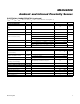
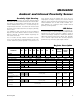
ELECTRICAL CHARACTERISTICS (continued)
(
V
DD
= 1.8V, T
MIN
– T
MAX
= -40°C to +105°C, T
A
= +25°C, unless otherwise noted.) (Note 1)
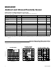
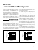
Typical Operating Characteristics
(V
DD
= 1.8V, T
MIN
– T
MAX
= -40°C to +85°C, unless otherwise noted. All devices are 100% production tested at T
A
= +25°C
.
Temperature limits are guaranteed by design.)
SPECTRUM RESPONSE
MAX44000 toc01
WAVE LENGTH (nm)
NORMALIZED OUTPUT
970870770670570470370
20
40
60
80
100
120
0
270 1070
GREEN CHANNEL
RED CHANNEL
CIE CURVE
ADC COUNT vs. DISTANCE
vs. LED DRIVE CURRENT
MAX44000 toc02a
DISTANCE (mm)
ADC COUNT
12010080604020
50
100
150
200
250
300
0
0 140
I
OUT
= 110mA
I
OUT
= 50mA
I
OUT
= 20mA
ADC COUNT vs. DISTANCE vs. OBJECT
MAX44000 toc02b
ADC COUNT
9080706050403020100 100
DISTANCE (mm)
50
100
150
200
250
300
0
GREY CARD
WHITE CARD
PARAMETER SYMBOL CONDITIONS MIN TYP MAX UNITS
I
2
C TIMING CHARACTERISTICS
Serial-Clock Frequency f
SCL
400 kHz
Bus Free Time Between STOP
and START
t
BUF
1.3
Fs
Hold Time (Repeated) START
Condition
t
HD,STA
0.6
Fs
Low Period of the SCL Clock t
LOW
1.3
Fs
High Period of the SCL Clock t
HIGH
0.6
Fs
Setup Time for a REPEATED
START
t
SU.STA
0.6
Fs
Data Hold Time t
HD,DAT
0 0.9
Fs
Data Setup Time t
SU,DAT
100 ns
SDA Transmitting Fall Time t
F
I
SINK
P 6mA, t
R
and t
F
between 0.3 x V
DD
and 0.7 x V
DD
100 ns
Setup Time for STOP Condition t
SU,STO
0.6
Fs
Pulse Width of Suppressed Spike t
SP
0 50 ns
MAX44000
4
Maxim Integrated