
Datasheet


Ambient and Infrared Proximity Sensor
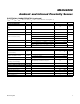
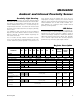
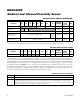
Pin Description
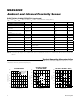
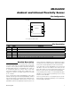
Pin Configuration
Detailed Description
The MAX44000 combines a wide-dynamic range ambi-
ent light sensor with an integrated infrared proximity
sensor. The die is placed inside an optically transparent
(UTDFN-Opto) package. A photodiode array inside the
IC converts the light to a current, which is then pro-
cessed by low-power circuitry into a digital value. The
data is then stored in an output register that is read by
an I
2
C interface.
The IC contains three types of photodiodes: a green pho-
todiode and two types of infrared photodiodes. Ambient
light sensing (ALS) is accomplished by subtracting the
infrared ALS photodiode signal from the green ALS
photodiode signals after applying respective gains. The
infrared proximity photodiodes are optimized for better
sensitivity for near infrared signals, specifically 850nm,
and can be used for proximity sensor measurements.
In the ALS mode, the ALS photodiodes are connected to
two ADCs. The user can choose to view either just the
green ALS signal, or just the infrared ALS signal, or the
difference of the green and infrared ALS photodiodes.
In the proximity detect mode, the infrared proximity pho-
todiodes are connected to the proximity receiver circuit
and then to an 8-bit ADC.
Three key features of the IC’s analog design are its low-
power design, single-pulse proximity receive operation,
and interrupt pin operation.
V
DD
SDA
6
1
GND SCL
5
2
DRV
*EP = EXPOSED PAD, CONNECT TO GND.
EP*
4
3
TOP VIEW
MAX44000
INT
+
PIN NAME FUNCTION
1 V
DD
Power Supply
2 GND Ground
3 DRV IR LED Current Driver
4
INT
Interrupt. Active-low output.
5 SCL I
2
C Clock
6 SDA I
2
C Data
EP — Exposed Pad. EP is internally connected to GND. EP must be connected to GND.
MAX44000
Maxim Integrated
7