
Datasheet


MAX4810/MAX4811/MAX4812
Dual, Unipolar/Bipolar, High-Voltage
Digital Pulsers
4 _______________________________________________________________________________________
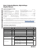
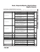
ELECTRICAL CHARACTERISTICS (continued)
(V
DD
= +2.7V to +6V, V
CC_
= +4.75V to +12.6V, V
EE_
= -12.6V to -4.75V, V
NN_
= -200V to 0, V
PP_
= 0 to (V
NN_
+ 200V), V
SS
≤ the lower of
V
NN1
or V
NN2
, T
A
= T
J
= T
MIN
to T
MAX
, unless otherwise noted. Typical values are at T
A
= +25°C.) (Note 3) (See Figures 8, 9, and 10.)
PARAMETER
SYMBOL
CONDITIONS
MIN TYP MAX UNITS
I
OP _
= - 100m A, V
C C _
= + 12V ± 5%, D C - coup l ed
10.5
17
High-Side Small-Signal Output
Impedance
R
OHS
I
OP _
= - 100m A, V
C C _
= + 5V ± 5%, D C - coup l ed 12 18
Ω
Low-Side Output Current I
OL
V
CC_
= +12V ±5%, V
OUT_
- V
NN_
= 100V 1.3 A
High-Side Output Current I
OH
V
CC_
= +12V ±5%, V
OUT_
- V
PP_
= 100V 1.3 A
MAX4810 45
Off-Output Capacitance
C
O
(
OFF
)
OP_, ON_, OCP_ and OCN_
connected together,
V
PP_
= +100V, V
NN_
= -100V
MAX4811 75
pF
Off-Output Leakage Current I
LK
V
NN_
= -100V, V
PP_
= 100V, EN_
= 0,
OUT = -100V to +100V
-1 +1 µA
I
OC N _
= - 100m A, D C - coup l ed , V
C C _
= + 12V ± 5% ,
V
E E _
= - V
C C _
22 50
Low-Side Signal-Clamp Output
Impedance
R
CLS
I
OCN_
= -100mA, DC-coupled, V
CC_
= +5V ±5%,
V
EE_
= -V
CC_
24 65
Ω
I
OC P _
= - 100m A, D C - coup l ed , V
C C _
= + 12V ± 5% ,
V
E E _
= - V
C C _
28 50
High-Side Signal-Clamp Output
Impedance
R
CHS
I
OCP_
= -100mA, DC-coupled, V
CC_
= +5V ±5%,
V
EE_
= -V
CC_
38 65
Ω
V
CC_
= +12V ±5%, V
EE_
= -V
CC_
, I
CGN
= 10mA,
EN_ = 0
100
Ω
Low-Side Gate Short
Impedance
R
LSH
V
CC_
= +12V ±5%, V
EE_
= -V
CC_
, I
CGN
= 10mA,
EN_ = V
DD
57.510k
Ω
V
CC_
= +12V ±5%, V
EE_
= -V
CC_
, I
CGN
= 10mA,
EN_ = 0
100
Ω
High-Side Gate Short
Impedance
R
HSH
V
CC_
= +12V ±5%, V
EE_
= -V
CC_
, I
CGN
= 10mA,
EN_ = V
DD
57.510k
Ω
THERMAL SHUTDOWN
Thermal Shutdown
T
SHDN
Junction temperature rising
150
°C
Thermal-Shutdown Hysteresis 20 °C
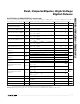
DYNAMIC CHARACTERISTICS (R
L
= 100
Ω
, C
L
= 100pF, unless otherwise noted)
Logic Input to Output Rise
Propagation Delay
t
PLH
V
CC_
= +12V, V
PP_
= +5V, V
NN_
= -5V, Figure 4
15 ns
Logic Input to Output Fall
Propagation Delay
t
PHL
V
CC_
= +12V, V
PP_
= +5V, V
NN_
= -5V, Figure 4
15 ns
Logic Input to Output Rise
Propagation Delay
t
POH
V
CC_
= +12V, V
PP_
= +5V, V
NN_
= -5V, Figure 4
15 ns
Logic Input to Output Fall
Propagation Delay
t
POL
V
CC_
= +12V, V
PP_
= +5V, V
NN_
= -5V, Figure 4
15 ns
Logic Input to Output-Rise
Propagation Delay Clamp
t
PLO
V
CC_
= +12V, V
PP_
= +5V, V
NN_
= -5V, Figure 4
15 ns